background image

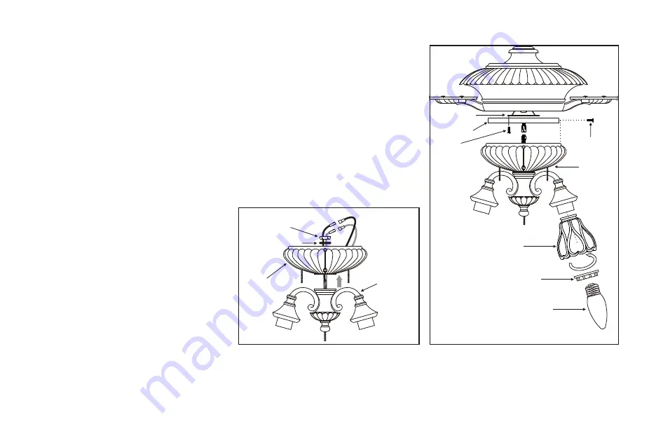
9. Installing the Light Kit

N O T E

:   B e f o r e   s t a r t i n g   i n s t a l l a t i o n ,  

disconnect the power by turning off the circuit 
breaker or removing the fuse at fuse box.

Turning power off using the fan switch is 
not sufficient to prevent electric shock.

1. Attach the light kit to the switch housing by 

feeding the light kit wires (black and white) 
through the hole of switch housing and then 
screw it onto the switch housing by nut & 
lock washer.  Be sure it is tight enough to 
prevent light kit from vibrating loose. (Fig. 
16)

2. Locate two single white and blue wires in 

the switch housing labeled  FOR LIGHT 

3. Make the polarized plug connections:
     - White to white  
     - Blue to black

4. Attach the metal plate to the plate holder 

with 3 screws provided, be sure to slide the 
metal plate over the screws and rotate 
clockwise until tight.

5. Carefully push all wires back into the 

switch housing, then install the light kit 
assembly onto the metal plate with 4 screws 
provided. Be sure to tighten all screws. (Fig. 
17) 

6.Remove the lock ring from the socket by 

turning the lock ring counter-clockwise 
until it unlocks.  Insert the glass into the 
glass holder and turn the lock ring 
clockwise to tighten the glass.  Repeat for 
the remaining glass.  (Fig. 17)

7. With the power off, insert the light bulbs 

(not included) into the light kit sockets.  
Max. 60 watts.

8. Restore power and your light kit is ready 

for operation.

9. If the light kit does not work, turn off the 

electricity and lower either canopy or 
decorative housing on your ceiling fan to 
make sure the blue wire is connected to the 
black household wire. 

Figure 17

Metal plate

Plate holder

Screws

Screws

Lock ring

Bulbs

Light kit 
assembly

Figure 16

Switch housing

Light kit

Nut

Lock washer

Glass shade

Содержание 285-962

Страница 1: ... peeling Brass finishes of this type give their longest useful life when protected from varying weather conditions A certain amount of wobble is normal and should not be considered a defect Servicing performed by unauthorized persons shall render the warranty invalid There is no other express warranty The retailer hereby disclaims any and all warranties including but not limited to Those of mercha...

Страница 2: ...Safety Rules Unpacking Your Fan Installing Your Fan Installing the Light Kit Care of Your Fan Troubleshooting Specifications Operating Your Fan 1 2 3 9 10 11 12 13 Table of Contents ...

Страница 3: ...when cleaning the fan or fan blades A dry dust cloth or lightly dampened cloth will be suitable for most cleaning 11 After marking electrical connections spliced conductors should be turned upward and pushed carefully up into outlet box The wires should be spread apart with the grounded conductor and the equipment grounding conductor onone side ofthe outlet box 12 Electrical diagrams are reference...

Страница 4: ... motor assembly 7 Metal plate Light kit Glass shade 4 Pull chain and fob 3 Balancing kit 8 Switch housing assembly 9 10 11 12 13 Switch housingcenter hole cover finial 14 Loose partsbag containing a Blade attachmenthardware 16 screws 16fiber washers b Mounting hardware 3 plasticwire connectors WARNING DO NOT INSTALL ORUSE FAN IF ANYPARTIS DAMAGED ORMISSING CALL TOLLFREE 877 898 1881 a b 14 3 1 2 5...

Страница 5: ...let box and its support must be able to fully support the moving weight of the fan at least 50 lbs Do not use plastic outlet boxes Figures 1 2 and 3 are examples of different ways to mount the outlet box Note You may need a longer downrod to maintain proper blade clearance when installing on asteep sloped ceiling To hang your fan where there is an existing fixture but no ceiling joist you may need...

Страница 6: ...NING ANDPOSSIBLYFALLING Step 8 Tighten two set screws on top of the fan motor firmly Figure7 Step 9 Place the downrod ball into the hanger bracket socket CHANGING THE DOWNROD OPTIONAL NOTE Your fan comes with a 4 downrod attached to the hanger ball In addition you have been provided with a 6 downrod to use if desired If you choose to use the 6 downrod perform the followingsteps 1 Remove the hanger...

Страница 7: ...an ground wire green to the household ground wire Step 4 After connecting the wires spread them apart so that the green and white wires are on one side of the outlet box and the black and the blue wires are on the otherside Step 5 Turn the connecting nuts upward and push the wiring into the outletbox Figures 9 and 10 illustrate the wiring connections for optional wall control available at your Ham...

Страница 8: ...Finishing the Installation Step 1 Tuck connections neatly into ceiling outlet box Step 2 Slide the canopy up to ceiling and over the 2 screws on hanger bracket Rotate canopy clockwise next while holding the canopy with one hand slide the canopy cover over the screws and rotate clockwise until tight Note adjust the canopy screws as necessary until the canopy and canopy cover are snug Fig 11 WARNING...

Страница 9: ... secure 2 Most fan wobble problems are caused when blade levels are unequal Check this level by selecting a point on the ceiling above the tip of one of the blades Measure this distance as shown in Figure 14 Rotate the fan until the next blade is positioned for measurement Repeat for each blade The distance should beequal within 1 8 If all blade levels are not equal you can adjust the blade level ...

Страница 10: ...Blade Balancing Kit if the blade wobbleis still noticeable 4 If the blade wobble is still noticeable interchanging two adjacent side by side blades can redistribute the weight and possibly result insmoother operation WARNING TO REDUCE THERISK OF PERSONALINJURY DO NOT BENDTHE BLADE HOLDERS WHILE INSTALLING BALANCING THE BLADES OR CLEANINGTHE FAN DO NOT INSERT FOREIGNOBJECTS BETWEEN ROTATING FANBLAD...

Страница 11: ...over the screws and rotate clockwise until tight 5 Carefully push all wires back into the switch housing then install the light kit assembly onto the metal platewith 4 screws provided Be sure to tightenall screws Fig 17 6 Remove the lock ring from the socket by turning the lock ring counter clockwise until it unlocks Insert the glass into the glass holder and turn the lock ring clockwise to tighte...

Страница 12: ...An upward airflow moves warm air off the ceiling area as shown in Figure 21 This allows you to set your heating unit on a lower setting without affecting your comfort Figure 18 Lighted housing bulb replacement 1 Locate fourbulb access coverson top of motor housing 2 Remove twoscrews that holdaccess cover near burned outbulb 3 Replace bulbwith 15W 120VAC candelabra bulb only 4 Reattach accesscover ...

Страница 13: ...ish The plating is sealed with a lacquer to minimize discoloration or tarnishing Do not use water when cleaning This could damage the motor or the wood or possibly cause an electrical shock 3 You can apply a light coat of furniture polish to the wood blades for additional protection and enhanced beauty Cover small scratches with a light application of shoe polish 4 There is no need to oil your fan...

Страница 14: ...are not rubbingagainst each otheror the interiorwall of theswitch housing CAUTION Make suremain power isoff 4 Allowa 24 hour breaking in period Most noiseassociated with anew fan disappearduring this time 5 If usingan optional lightkit make surethe screws securingthe glassware aretight Check thatlight bulb is also secure 6 Some fan motorsare sensitive tosignals from solid statevariable speed contr...

Страница 15: ...RPM CFM N W G W C F 52 120 2 52 kgs kgs 120 120 Fan Size Speed Volts Amps Watts Low Medium High 13 Specifications Distributed by Home Depot U S A Inc 2455 Paces Ferry Rd N W Atlanta Georgia 30339 2005 Homer TLC Inc All Rights Reserved Hampton Bay is a registered trademark of Homer TLC Inc C ...

Отзывы: