Hammond Manufacturing HWC Series Скачать руководство пользователя страница 9

HWC - SERIES

REV.

BUL87423

C

INSTRUCTIONS FOR

HWC

PAGE    OF 9

9

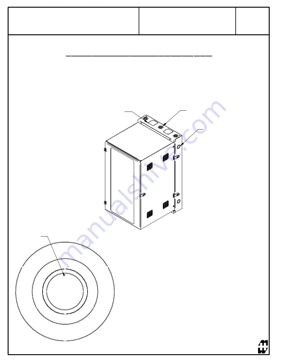
KNOCK-OUTS AND CABLE WAYS

Fan Mounting KO

Knock-outs are located on the top/bottom and sides of the rear section.

The openings allow for cable entry, mounting of conduits, and fan
mounting.

Proper Removal of Knock-Outs

When removing an inner knock-out with the intent to leave the
larger intact, ensure the force is applied to the weakest area of
the ring.

This is accomplished by placing the knock-out tool as far away
from the tabs as possible while remaining as close to the tab of
the next largest ring (shown to the left).

Apply Force Here

Quadruple KO

3", 2", 1.38", and 1.12" KO

2.5" and 2" KO

Содержание HWC Series

Страница 1: ...ES INSTRUCTIONS FOR HWC 1 visit our website visitez notre site Web www hammondmfg com Item Number Title Quantity 1 HWC REAR MOUNT ASSY 1 2 HWC CENTRE SECTION 1 3 HWC RAIL TAPPED 2 4 HWC WINDOW DOOR AS...

Страница 2: ...rdance with Article 250 of the National Electric Code To reduce risk of personal injury and product damage always ensure a a sufficient amount of personnel are present when loading unloading and movin...

Страница 3: ...INSTRUCTIONS FOR HWC 3 visit our website visitez notre site Web www hammondmfg com 1 TOOL BOX LEVEL NIVEAU WALLMOUNT INSTRUCTIONS OPTIONAL Remove front section of wallmount to allow for an easier inst...

Страница 4: ...rews Mount back pan using 3 8 dia lag bolts and standard flat washers 16 TEMPLATE MOD LE 2 LEVEL NIVEAU FRAN AIS Les diff rents mat riaux de paroi murale n cessitent diff rents types de vis Monter l a...

Страница 5: ...HWC SERIES REV BUL87423 C INSTRUCTIONS FOR HWC PAGE OF 9 5 4...

Страница 6: ...HWC SERIES REV BUL87423 C INSTRUCTIONS FOR HWC PAGE OF 9 6 REVERSE MIDDLE SECTION INSTRUCTIONS 1 2 3 180v...

Страница 7: ...ECTION SHALL BE ATTACHED FIGURE 1 NOTE ALL PROTECTIVE EARTH AND BONDING CONNECTIONS SHALL BE IN ACCORDANCE WITH ARTICLE 250 OF THE NATIONAL ELECTRIC CODE 1 Included within optional grounding kit GRDKI...

Страница 8: ...ion Attach bonding wire found in ground kit to a centre section bonding stud closest to the hinged side of the enclosure using the ring terminal and hardware provided Attach opposite end of wire to th...

Страница 9: ...nduits and fan mounting Proper Removal of Knock Outs When removing an inner knock out with the intent to leave the larger intact ensure the force is applied to the weakest area of the ring This is acc...

Отзывы: