10
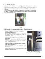
The brush motors are switched on and off by a micro-switch located at the rear at the brush head
lift-out system. This switch is realised as NO (normally open) switch. To attain safe function of the
brush motors, correct adjustment of this switch is required.
Electric connection of the switch is realised at the central control at A1.X9:4 + 10.
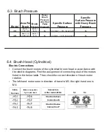
Maximum current consumption of the brush motors (in practical use) must not exceed 30A per
motor on the
disk brush decks.
Lower settings are recommended for longer motor life, run time and traction.
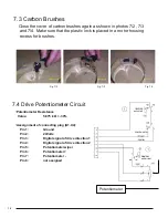
When checking the carbon brushes make sure that the scroll spring is pressing the carbon brush
against the commutator, does not contact the guide and that distance to carbon brush guide is
sufficient.
Replace the carbon brushes, if required.
5.1
Brush Motor Information
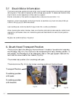
The lever provided is for lifting up the brush head. It features 3 positions for adjusting
the lift linkage (Fig. 6/1). The top hole is the transporting and ramp climbing position. In
this position, the lift linkage is to be adjusted so that a 1mm gap appears between the
lever and the screw head at the chassis (Fig. 6/2).
The middle hole position is for scrubbing with pads.
The bottom hole (Fig. 6/1) is the normal scrubing position of the brush head.
6. Brush Head Transport Position
1 mm
Fig. 6/2
Transport Position
Scrubbing position
with pads
Scrubbing position
with brushes
Fig. 6/1
Содержание 650RS
Страница 5: ...5 3 2 System Maintenance I 3 3 System Maintenance II...
Страница 17: ...17 10 Table of Error Codes...
Страница 18: ...18 11 24V 22A Charger 10 1 Operating Instructions 11 1 24V 22A Charger...
Страница 28: ...28...
Страница 29: ...28 17 Contactor Wiring Control Board To batteries and charger Proper wiring of the contactor is critical...
Страница 30: ...CONT ACT US 800 626 7835 Contact HammerHeadClean com HammerHeadClean com HAMMERHEAD ENGINEERED SIMPLICITY...


