


18
08-315 (3/6/12)
Service Adjustments
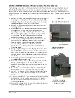
A momentary service/mirror switch on the bottom left side of the
video head (see Figure 22) disconnects the external wiring
and internally connects the camera to the monitor for testing
purposes.
The service/mirror switch does not exist on the
5550-1 since no camera is present.
he monitor has been adjusted at the factory but a menu
board allows settings to be changed if needed. The menu
board is attached to the plate on the rear of the LCD. See the
section “5550/5517 LCD Menu Adjustments” for more
information.
The camera has been adjusted at the factory but a camera
menu board
(only available on later units)
attached to the
plate on the rear of the LCD screen allows camera settings to
be changed if needed. See Figure 23 for an explanation of the menu buttons. Use the service/mirror
switch or press the audio console hold button (with no lane selected) to connect the camera to the
monitor for viewing the menu. If focusing is required, loosen the small set screw on top of the lens
and then rotate the lens to the desired focus. Snug the set screw when finished but do not over
tighten to avoid creating a dimple in the lens threads making future fine adjustments difficult.
Figure 22
Service / Mirror
Switch
Power
Switch
DOWN
LEFT
RIGHT
UP
SET
Figure 23
SET:
Used to enter the OSD menu and select menu or submenu items.
UP:
Used to move up a line in a menu or submenu.
DOWN: Used to move down a line in a menu or submenu.
LEFT: Used
to
change setting values.
RIGHT: Used
to
change setting values.
Tip: Selecting “Reset from the “Special” menu returns all settings to their factory
values.
Camera Menu Board


