53
Subject to change without notice
S e r i a l b u s a n a l y s i s
If you choose the binary input, the soft menu key
SELECT BIT
and the universal knob allow you to select which individual bits
within the data are to be edited. The option STATE allows you
to assign a logic state to each bit (High = H = 1, Low = L = 0 or
X = don’t care). The state X defines any state. If you choose the
hexadecimal input, the soft menu key VALUE and the
universal
knob allow you to set the value for the respective nibble (4 bit).
If the input is hexadecimal, only the entire
nibble can be set to
X. Use the soft menu key
SELECT NIBBLE
to toggle between
nibbles. The active nibble will be marked with a green border in
the display window of the trigger condition (see fig. 13.15). Press
the MENU OFF button three times to close all menus, and the
oscilloscope will trigger on the set bit sequence.
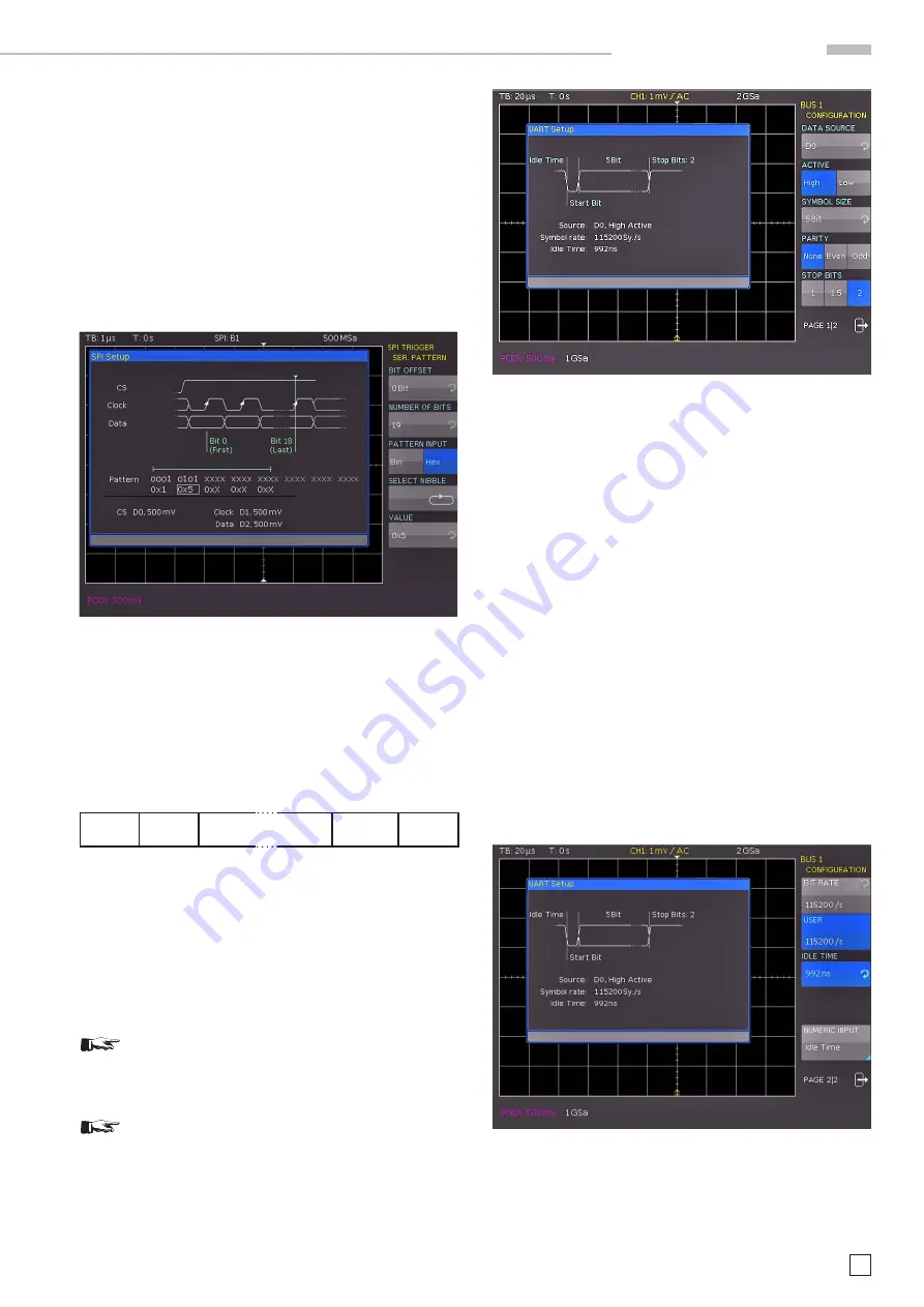
Fig. 13.15: SPI data trigger menu
13.5 UART/RS-232 BUS
The UART (Universal Asynchronous Receiver Transmitter) bus
is a general bus system and the base for many protocols. One
example is the RS-232 protocol. It consists of a frame with a
start bit, 5 to 9 data bits, one
parity bit and a stop bit. The stop
bit can assume the single length, or 1.5 or twice the length of
a normal bit.
S t a r t D a t a 0 D a t a 1 [ D a t a 8 ] [ Pa r i t y ] S t o p
Fig. 13.16: UART bit sequence
The HMO series supports bit rates of 9600 bit/s, 115.2 kBit/s
and 1 MBit/s (for measurements without measuring object via
BUS SIGNAL SOURCE). Use the soft menu PROBE COMP &
BUS SIGNAL SOURCE to select the respective clock rate in the
SETUP menu (page 2|2).
13.5.1 UART/RS-232 BUS Configuration
Prior to the BUS configuration it is necessary to set
the correct logic level for the digital channels (see
chapter 11.2) or the analog channels (see chapter
4.5). The default setting for both is 500 mV.
Make sure that a complete message of a serial pro-
tocol is always displayed on the screen to ensure
decoding can function properly. The Zoom function
allows you to view details for any specific message.
To decode the UART BUS it is necessary to first determine
which channel will be connected to the data line. This setting
is selected after choosing the bus type UART in the BUS menu
and pressing the soft menu key
CONFIGURATION
. In the menu
that opens you can press the top soft menu key
DATA SOURCE
to select the desired channel via universal knob. If the option
HOO10 is installed, each analog and digital channel is available
as
source. If the option HOO11 is installed, it is only possible to
select analog channels as source.
The soft menu key ACTIVE can be used to determine if the data
transfered to the BUS are active high (High = 1) or active low
(Low = 1), (for RS-232, choose Low). Use the soft menu key
SYMBOL SIzE and the
universal knob to select a value between
5 bit to 9 bit for the bits that form a symbol. Another setting can
be selected via soft menu key
PARITY
. Parity bits are used to
detect errors during a transmission.
The soft menu PARITY offers the following options:
–
None
: Use no parity bits
–
Even
: The parity bit is set to “1” if the number of ones in a
specific set of bits is uneven (without
parity bit)
–
Odd
: The parity bit is set to “1” if the number of ones in a
specific set of bits is even (without
parity bit)
The bottom soft menu key
STOP BITS
allows you to define the
length of the stop bit (1 = single, 1.5 = 1 1/2 or 2 = double).
Fig. 13.18: Page 2|2
UART BUS setup menu
On page 2|2 of the UART BUS setup menu, you can select the
BIT RATE
(symbol rate) via
universal knob. The bit rate defines
how many bits are sent per second. The soft menu key BIT
RATE allows you to select standard numeric values. Press the
Fig. 13.17: Page 1 of the menu to define a UART bus


