


44
Subject to change without notice
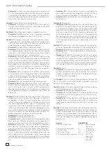
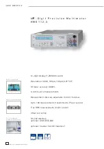
thermo-
couples
V
A
SENSE
SOURCE
LO
HI
max.
250Vrms
max.
850
Vpk
max.
850
Vpk
Ω
,
ϑ
FUSE
1A
F250V
CAT
II
max. INPUT
600Vrms / 1Arms
+
Continuity
test
–
STOP
STOP
Test voltage
(open circuit):
2.5 V
Measurement
period:
100 ms to 60 s
Delay:
100 ms (after change of function or range)
Calibration:
with resistance measurement standard
PT100 1
k
Ω
range
PT1000
10
k
Ω
range
Linearisation: according
to
EN60751
ϑ
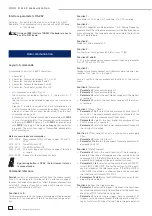
PT with 2-wire-temperature measurement
Limited accuracy of measured values for 2-wire-temperature
measurement with platinum temperature sensors PT100 or
PT1000.
Adjustment of measuring section with PT sensor
PT sensors have an output resistance which is mostly referred
in the data sheet. Often the data sheet is lost but the sensor is
still there. In HM8112-3 a value of 100 m
Ω
is stored by default.
But some PT sensors have an integrated series resistance
(e.g. 10 m
Ω
). For an optimal adjusted measuring section the
exact output resistance must be known. This applies for 4-wire
measurement but especially for 2-wire measurements. Via
interface the default value stored ex factory can be aligned.
Values between 0 m
Ω
and 100 m
Ω
are possible.
Determination of the output resistance
The PT100 or PT1000 sensor has to be immersed in an ice
bath. At 0 °C the sensor has a resistance of 100
Ω
and 1000
Ω
respectively. The resistance of the temperature sensor is taken
by a resistance measurement. The output resistance is the dif-
ference between the measured value and the specifi ed value.
ϑ
TH temperature measurement with thermocouples
Measuring method:
Voltage measurement in 100 mV
range with linearisation according to
EN60584.
Display range:
Thermocouples
Range up to °C
J- Type (Fe-CuNi)
–210 to +1200
K – Type (NiCr-Ni)
–270 to +1372
Resolution:
0.1 °C / °F
Measurement period:
100 ms to 60 s
Delay:
100 ms (after change of function)
Display:
Dimension °C or °F
Linearisation:
according to EN60584
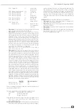
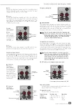
V
A
SENSE
SOURCE
LO
HI
max.
250Vrms
max.
850
Vpk
max.
850
Vpk
Ω
,
ϑ
FUSE
1A
F250V
CAT
II
max. INPUT
600Vrms / 1Arms
+
–
Power
input
(Source)
Continuity test
Continuity and diode test
Continuity test:
Activating of the loudspeaker for measured values between
0
Ω
(short-circuit) and approx. 10
Ω
.
Diode test:
Test voltage approx. 2.5 V
Test current 1 mA constant
Max. forward voltage 1.2 V, otherwise
“Overfl ow V
DC
“ is displayed.
The test unit must be at zero potential during conti-
nuity test.
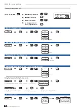
Max / Min values
MAX /
MIN
The maximum or minimum measured value is displayed. As
this is possible in every measurement function, a system can
be controlled with respect to min/max values. There is no time
limitation, e.g. for activating this function for one year, the
minimum or maximum value measured during this year will
be displayed. This function is deactivated by pushing the keys
MAX
or MIN
again. Changing the measurement function
will deactivate this function, too.
Range selection
Manual range selection
The range can be selected manually by pressing
and
.
Switch to a lower range. The auto range function will
be deactivated.
Switch to a higher range. The auto range function will
be deactivated.
If the applied measurement value exceeds the range, the display
will show „Overfl ow“.
AUTO
With button AUTO the auto range function can be activated.
This function is selectable for voltage, current and resistance
measurements.
As the autorange function is activated a higher range will be
selected after the measured value exceeds 90% of full scale. The
HM8112-3 will change to a lower range, if the value falls below
10% of full scale. If the signal applied exceeds the specifi ed
limits of the instrument in the autorange function, the display
shows “overfl ow“.
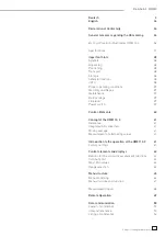
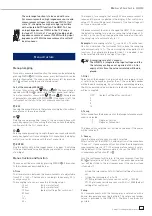
V
A
SENSE
SOURCE
LO
HI
max.
250Vrms
max.
850
Vpk
max.
850
Vpk
Ω
,
ϑ
FUSE
1A
F250V
CAT
II
max. INPUT
600Vrms / 1Arms
+
–
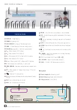
C o n t r o l e l e m e n t s a n d d i s p l a y