Hameg HM1507-3 Скачать руководство пользователя страница 26

Subject to change without notice

28

The output provides 0.2V

pp

 ±1% (tr <4ns) for 10:1 probes.

When the Y deflection coefficient is set to 5mV/div, the
calibration voltage corresponds to a vertical display of 4
divisions (10:1 probe).

The output socket has an internal diameter of 4.9mm to
accommodate the internationally accepted shielding tube
diameter of modern Probes and F-series slim line probes.
Only this type of construction ensures the extremely short
ground connections which are essential for an undistorted
waveform reproduction of non-sinusoidal high frequency
signals.

Adjustment at 1kHz

The C-trimmer adjustment (low frequency) compensates the
capacitive loading on the oscilloscope input. By this
adjustment, the capacitive division assumes the same ratio
as the ohmic voltage divider to ensure the same division ratio
for high and low frequencies, as for DC. (For 1:1 probes or
switchable probes set to 1:1, this adjustment is neither
required nor possible). A baseline parallel to the horizontal
graticule lines is essential for accurate probe adjustments.
(See also 

“Trace rotation TR”

).

Connect the probes (Types HZ51, 52, 54, or HZ36) to the
CH I input. Set the deflection coefficient to 5mV/div and the
input coupling to DC. The time deflection coefficient should
be set to 0.2ms/div. All deflection coefficients should be
calibrated. Plug the probe tip into the calibrator output socket.

Approximately 2 complete waveform periods are displayed
on the CRT screen. The compensation trimmer should be
adjusted. The location of the low frequency compensation
trimmer can be found in the probe information sheet. Adjust
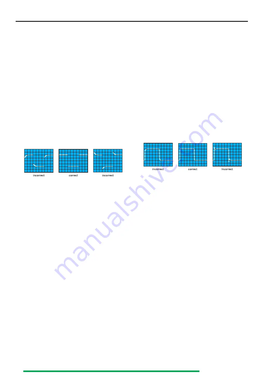
the trimmer with the insulated screw driver provided, until
the tops of the square wave signal are exactly parallel to the
horizontal graticule lines (see 1kHz diagram). The signal height
should then be 4div ± 0.16div (= 4% (oscilloscope 3% and
probe 1%). During this adjustment, the signal edges will
remain invisible.

Adjustment at 1MHz

Probes HZ51, 52 and 54 can also be HF-compensated. They
incorporate resonance de-emphasing networks (R-trimmer
in conjunction with inductances and capacitors) which permit
probe compensation in the range of the upper frequency limit
of the vertical oscilloscope amplifier. Only this compensative
adjustment ensures optimum utilization of the full bandwidth,
together with constant group delay at the high frequency
end, thereby reducing characteristic transient distortion near
the leading edge (e.g. overshoot, rounding, ringing, holes or
bumps) to an absolute minimum.

Using the probes HZ51, 52 and 54, the full bandwidth of the
oscilloscope can be utilized without risk of unwanted wave-
form distortion.

Prerequisite for this HF compensation is a square wave
generator with fast rise time (typically 4ns), and low output
impedance (approx. 50

), providing 0.2V at a frequency of

approx. 1MHz. The calibrator output of this instrument meets

these requirements when the 

CAL.

 pushbutton is depressed.

Connect the probe to 

CH.I

 input. Depress the 

CAL.

pushbutton for 1MHz. Operate the oscilloscope as described
under 1kHz but select for 0.2µs/div time deflection coefficient
setting.

Insert the probe tip into the output socket. A waveform will
be displayed on the CRT screen, with leading and trailing
edges clearly visible. For the HF-adjustment now to be per-
formed, it will be necessary to observe the rising edge as
well as the upper left corner of the pulse top. The location of
the high frequency compensation trimmer(s) can also be
found in the probe information sheet. These R-trimmer(s)
have to be adjusted such that the beginning of the pulse is
as straight as possible. Overshoot or excessive rounding are
unacceptable. The adjustment is relatively easy if only one
adjusting point is present. In case of several adjusting points
the adjustment is slightly more difficult, but causes a better
result. The rising edge should be as steep as possible, with a
pulse top remaining as straight and horizontal as possible.
After completion of the HF-adjustment, the signal amplitude
displayed on the CRT screen should have the same value as
during the 1kHz adjustment.

Probes other than those mentioned above, normally have a
larger tip diameter and may not fit into the calibrator output.
Whilst it is not difficult for an experienced operator to build a
suitable adapter, it should be pointed out that most of these
probes have a slower rise time with the effect that the total
bandwidth of scope together with probe may fall far below
that of the oscilloscope. Furthermore, the HF-adjustment
feature is nearly always missing so that waveform distortion
can not be entirely excluded. The adjustment sequence must
be followed in the order described, i.e. first at 1kHz, then at
1MHz. The calibrator frequencies should not be used for time
base calibration. The pulse duty cycle deviates from 1:1 ratio.

Prerequisites for precise and easy probe adjustments, as well
as checks of deflection coefficients, are straight horizontal
pulse tops, calibrated pulse amplitude, and zero-potential at
the pulse base. Frequency and duty cycle are relatively un-
critical. For interpretation of transient response, fast pulse
rise times and low-impedance generator outputs are of
particular importance. Providing these essential features, as
well as switch-selectable output-frequencies, the calibrator
of the instrument can, under certain conditions, replace
expensive square wave generators when testing or
compensating wide-band attenuators or -amplifiers. In such
a case, the input of an appropriate circuit will be connected
to the 

CAL.

-output via a suitable probe.

The voltage provided at a high-impedance input (1M

 II 15-

30pF) will correspond to the division ratio of the probe used
(10:1 = 20mVpp output). Suitable probes are HZ51, 52, and
54.

Operating modes of the vertical

amplifiers in Yt mode

The most important controls regarding the operation modes
of the vertical amplifiers are the pushbuttons: 

CHI (22), DUAL

(23) and CH II (26)

. Their functions are described in the

section

 “ Controls and Readout”

.

First Time Operation

Содержание HM1507-3

Страница 1: ...ls 32 Line Mains triggering 32 Alternate triggering 32 External triggering 33 HOLD OFF time adjustment 33 B time base 2nd time base 33 Triggering after Delay 33 AUTO SET 34 Component Tester analog mod...

Страница 2: ...operation the following hints and conditions regarding emission and immunity should be observed 1 Data cables For the connection between instruments resp their interfaces and external devices computer...

Страница 3: ...Variable 2 5 1 up to 1 25s div X MAG x10 5 max 5ns div Holdoff time variable to approx 10 1 Bandwidth X amplifier 0 3MHz 3dB X Y phase shift 3 below 220kHz Digital Time Base Accuracy 3 1 2 5 sequence...

Страница 4: ...in a socket outlet provided with a protective earth contact The protective action must not be negated by the use of an extension cord without a protective conductor The mains line plug must be insert...

Страница 5: ...on ments The oscilloscope can be operated in any position but the convection cooling must not be impaired The ventilation holes may not be covered For continuous operation the instrument should be use...

Страница 6: ...wnwards at each change Pure direct voltages can only be measured with DC coupling The input coupling is selectable by the AC DC pushbutton The actual setting is displayed in the readout with the symbo...

Страница 7: ...In this case an appropriate high voltage capacitor approx 22 68nF must be connected in series with the input tip of the probe With Y POS control input coupling to GD it is possible to use a horizontal...

Страница 8: ...its full length at not too great steepness and that the horizontal distance at 10 and 90 of the amplitude is measured If the edge shows rounding or over shooting the 100 should not be related to the p...

Страница 9: ...as short and thick as possible When the attenuator probe is connected to a BNC socket a BNC adapter should be used In this way ground and matching problems are eliminated Hum or interference appearing...

Страница 10: ...and no other LED on the front panel is lit except A All INTENS settings are stored after the instrument is switched off The AUTO SET function switches the readout on and selects A time base mode A LED...

Страница 11: ...cally again it will be required to stop rotating the knob for at least about 2 seconds Attention The dynamic range limits of the A D converter may become visible if a Y position shift is performed af...

Страница 12: ...STOR MODE Pushbuttons with associated LEDs These functions are not available in analog mode If digital SINGLE SGL mode has not been chosen one of the associated LEDs is lit The signal capture and disp...

Страница 13: ...g mode on or off SINGLE mode is indicated by the associated SGL LED SINGLE mode is available in digital as well as in analog mode and remains unchanged when switching over from analog to digital mode...

Страница 14: ...tton until a beep confirms reference memory acquisition Before starting the procedure the current signal can but must not be protected by the HOLD function As the reference signal is then equal to the...

Страница 15: ...the DC content of a signal by comparing the actual Y position with the previously determined 0 Volt Y position Y POS I Symbol Provided that the readout is displayed and DC REFE RENCE ON is selected i...

Страница 16: ...control knob causes a different trigger point setting voltage The trigger unit starts the time base when the edge of a trigger signal voltage crosses the trigger point In most Yt modes the trigger po...

Страница 17: ...o GD 34 38 Whether alternated or chopped channel switching is present in analog mode depends on the actual time base setting and is displayed in the readout ALT analog mode only displayed in the reado...

Страница 18: ...e A B time base mode B time base mode and line mains trigger coupling STORAGE MODE ONLY In ROLL mode the signal capture is untriggered Con sequently alternate triggering is not available 25 VOLTS DIV...

Страница 19: ...start of the intensified sector In the free run condition delay trigger not active of the B time base an approximate value is displayed in the readout Dt This is an aid to find the position of the int...

Страница 20: ...information is also displayed in the readout as an approximate value e g Dt 2 5ms related to the calibrated A time coefficient uncalibrated i e Dt 2 5ms The width of the segment decreases when the B t...

Страница 21: ...on coefficient setting is not possible in storage mode Underneath the front panel sector described before the BNC sockets and four pushbuttons are located 32 INPUT CH I BNC socket This BNC socket is t...

Страница 22: ...he CRT there are the controls for the readout the component tester and the square wave calibrator with their outputs Please note The following description of the cursor related controls assumes that t...

Страница 23: ...nt must be activated Briefly pressing the CHI II 1 t ON OFF pushbutton switches from f to t and the following measure ment modes until the readout displays f again In all conditions vertical cursor li...

Страница 24: ...ayed in the readout must be multiplied by 100 if e g a x100 100 1 probe is used In case of x10 10 1 probes the probe factor can be automatically included see AC DC 33 and AC DC 37 t In time or frequen...

Страница 25: ...connect the test lead s to the test point s Then switch on the instrument and after wards the device under test The oscilloscope is switched on by depressing the red POWER pushbutton After a few seco...

Страница 26: ...tton is depressed Connect the probe to CH I input Depress the CAL pushbutton for 1MHz Operate the oscilloscope as described under 1kHz but select for 0 2 s div time deflection coefficient setting Inse...

Страница 27: ...are the same for both channels because the X x10 magnifier is inactive in XY mode The bandwidth of the X amplifier is lower than the Y amplifier and the phase angle which increases with higher freque...

Страница 28: ...l cycles of the modulation frequency are visible Strictly speaking triggering should be external with modulation frequency from the AF generator or a demo dulator However internal triggering is freque...

Страница 29: ...ger coupling setting In the absence of an adequate trigger signal or when the trigger controls particularly the trigger LEVEL control are misadjusted no trace is visible i e the screen completely blan...

Страница 30: ...ernal trigger voltage itself is displayed first with internal triggering In most cases the composite video signal has a high DC content With constant video information e g test pattern or color bar ge...

Страница 31: ...iting the trigger pulse This causes an untriggered display and a flashing trigger LED HOLD OFF time adjustment For instrument specific information please note DEL POS HO 28 in section Controls and Rea...

Страница 32: ...ically for a display of approx 2 signal periods The time base setting occurs randomly if complex signals consisting several frequencies e g video signals are present AUTO SET sets the instrument autom...

Страница 33: ...mination of actual values will come with experience or by direct comparison with a component of a known value Testing Capacitors and Inductors Capacitors and inductors cause a phase difference between...

Страница 34: ...ared with single components In case of doubt one component terminal may be unsoldered This terminal should then not be connected to the ground socket avoiding hum distortion of the test pattern Anothe...

Страница 35: ...d Controls Vertical resolution The dot density in each operation mode is 8 bits 28 256 dots displayed over a height of roughly 10 divisions The instrument is adjusted for 25 dots per division This eas...

Страница 36: ...k must on no account be visible Visible trace fault without input signal bright dot on the left side or decreasing brightness from left to right or shortening of the baseline Cause Incorrect Unblankin...

Страница 37: ...mitted This is achieved by adjusting the trimmer located in the 2 1 attenuator The shape of the square wave should then be the same in each input attenuator position Operating Modes CH I II DUAL ADD C...

Страница 38: ...Then both readout information regarding the time deflection coefficient and the time difference show exactly the same value After switching over from time to frequency measurement the readout display...

Страница 39: ...ng on of the oscilloscope and the first command SPACE CR 20hex 0Dhex sent from the PC the baud rate is recognized and set automatically between 110 baud and 19200 baud The oscilloscope is then switche...

Отзывы: