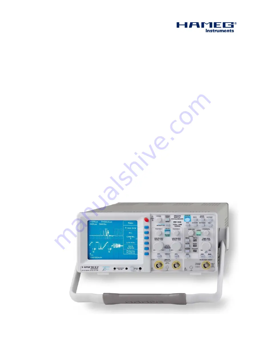
1 0 0 M H z C o m b i S c o p e
®
H M 1 0 0 8
Manual
English
Страница 1: ...100 MHz CombiScope HM1008 Manual English...
Страница 2: ...MC Directive 89 336 EEC amended by 91 263 EWG 92 31 EEC Directive EMC 89 336 CEE amend e par 91 263 EWG 92 31 CEE Niederspannungsrichtlinie 73 23 EWG erg nzt durch 93 68 EWG Low Voltage Equipment Dire...
Страница 3: ...Measurement of phase differences in dual channel Yt mode 14 Measurement of amplitude modulation 15 Triggering and time base 15 Automatic peak triggering MODE menu 15 Normal trigger mode See menu MODE...
Страница 4: ...me Base 50 s cm 5 ns cm Acquisition modes Single Event Refresh Average Envelope Roll Peak Detect RS 232 Interface optional USB RS 232 IEEE 488 Ethernet USB Signal display Yt and XY Interpolation Sinx...
Страница 5: ...e 50 ppm Display 1 MEMORY ZOOM max 50 000 1 Bandwidth X Amplifier 0 100 MHz 3 dB X Y phase shift 3 100 MHz Digital Storage Sampling rate real time 2x 500 MSa s 1 GSa s interleaved Sampling rate random...
Страница 6: ...Without pulling the locking knobs they will latch in into the next locking position Handle mounting dismounting The handle can be removed by pulling it out further depending on the instrument model in...
Страница 7: ...xplosion The operating position may be any however suf cient ventila tion must be ensured convection cooling Prolonged operation requires the horizontal or inclined position STOP Do not obstruct the v...
Страница 8: ...tes the current function of POSITION 1 and 2 controls VOLTS DIV SCALE VAR knob 32 Channel 1 Y de ection coef cient Y variabel and Y scaling setting VOLTS DIV SCALE VAR knob 32 Channel 2 Y de ection co...
Страница 9: ...Component Tester Left socket is galvanically connected with protective earth MEMORY oom COMPONENT TESTER PROBE ADJ C O M B I S C O P E POWER 38 39 40 EXIT MENU VOLTS DIV SCALE VAR VOLTS DIV SCALE VAR...
Страница 10: ...ich of course must have a suf cient dc rating Care must be taken however when charging and discharging a large capacitor Dc coupling is preferable with all signals of varying duty cyc le otherwise the...
Страница 11: ...ead the time difference In the example it was 1 6 cm at 5 ns cm equals 8 ns rise time When measuring very short rise times coming close to the scope rise time it is necessary to subtract the scope s a...
Страница 12: ...specially at high sen sitivity one possible reason may be multiple grounding The scope itself and most other equipment are connected to safety ground so ground loops may exist Also most instruments wi...
Страница 13: ...herefore please observe the following rule Always look at the two signals in the one channel only or the dual modes and make sure that they are within the permissible input signal range this is the ca...
Страница 14: ...ator with trigonometric functions This calculation is independent of the signal amplitudes Please note As the trigonometric functions are periodic limit the calculation to angles 90 degrees This is wh...
Страница 15: ...e time base variable or external triggering Reading a and b off the screen the modulation degree will result a b a b m bzw m 100 a b a b a UT 1 m and b UT 1 m When measuring the modulation degree the...
Страница 16: ...ve of the polarity of the next slope Rising slope means that a signal comes from a negative po tential and rises towards a positive one This is independent of the vertical position A positive slope ma...
Страница 17: ...ed with SOURCE Alt 1 2 The read out will display Tr alt but no more the trigger point symbol indicating level and time position Instead an arrow pointing upwards will indicate the trigger time positio...
Страница 18: ...time whereas a DSO can only show a reconstruction of the signal acquired some time later In analog mode thus the display will always start on the left Let us assume one period of a signal is displayed...
Страница 19: ...n this mode the Y ampli ers and the time base are turned off Only individual components may be tested i e they must not be part of a circuit if voltages are to be applied to the BNC connectors If the...
Страница 20: ...conduct if prior to testing the gate was connected to the source The Rdson will be shown As this can be very low it may look like a plain short although the part is good With enhancement type MOSFETs...
Страница 21: ...t the signal is a sine wave It is easily under stood that in order to depict an unknown signal shape one needs at least 1 or 2 points per centimeter in other words the useful signal frequency is only...
Страница 22: ...al capture is triggered in SINGLE REFRESH ENVELOPE and AVERAGE modes and untriggered in ROLL and XY modes The normal Refresh mode is similar to the operating mode of an analog scope Triggering will ca...
Страница 23: ...lained the maximum sampling rate must be reduced for slow time base settings This may cause aliases If e g a sine wave is sampled only with one sample per period and if it should be synchronous with t...
Страница 24: ...eters are N 8 2 no parity 8 bits data 2 stop bits RTS CTS hardware protocol Selection of Baud rate Baud rate setting is automatic Range 110 to 115200 no parity 8 bits data 2 stop bits The rst SPACE CR...
Страница 25: ...ess and will hence not cause a menu display STOP Please note If a menu is shown some other information dis played in the readout may disappear this will reappear immediately upon leaving the menu Each...
Страница 26: ...displayed by ZOOM digital mode only RO Int Readout intensity Focus Focus for signal and readout Readout On Off Turning the readout off will eliminate interference of the readout with the signal s The...
Страница 27: ...s blue The operating mode Yt or XY will not be affected If component test mode was selected possible only in analog mode and the scope is switched to digital the operating mode last used when in DSO m...
Страница 28: ...ntre With the 2nd acquisition the display will start at the screen left In most cases this is meaningless but the scope may seem not to react at slow time base settings combined with long Posttrigger...
Страница 29: ...without the need for a trigger Hence all controls displays and readouts for the trigger and ZOOM will be disabled The readout will show rol The result of the last acquisition will be displayed at the...
Страница 30: ...1 MByte samples may be acquired but only up to 2 KBytes per channel can be displayed hence possibly min or max values may not be shown Otherwise the display is as described above AUTOSET Choosing AUT...
Страница 31: ...Mathematics signal position DSO mode only The POSITION 1 control will assume the function of position con trol for mathematics signals after the following procedure Press the MATH pushbutton Display u...
Страница 32: ...alibrated The results of cursor measurements will be agged accordingly In this mode the sensitivity can be changed with the VOLTS DIV SCALE VAR control knob from 1 mV cm to 20 V cm 16 3 SCALE DSO mode...
Страница 33: ...AUTO CURSOR MEASURE pushbutton Pressing this pushbutton will open the menu Measurement which offers the submenus Cursors and Auto If the submenu Cursors was selected and a measuring mode Cursors On m...
Страница 34: ...n mode the level can only be selected between the signal s peak values The movement of the trigger symbol is vertical only The range of this symbol is limited in order to prevent that this symbol will...
Страница 35: ...ode of the scope C o n t r o l s a n d R e a d o u t any level can be set If the trigger level is set such that no trig gers are generated the automatic triggering will nevertheless start the time bas...
Страница 36: ...nly This display will light up if the hold off time was set to 0 in order to indicate that the longer than minimum hold off time may cause a lower rep rate of the time base and thus a darker display S...
Страница 37: ...the readout Z and is calibrated Turning the knob CCW will decrease turning it CW will increase the time base speed This can be selected from 20 ms cm to 5 ns cm in a 1 2 5 sequence The maximum expansi...
Страница 38: ...ded to the time base B display Press the CH1 2 CURSOR MA REF ZOOM pushbutton which calls the Pos Scale menu Press the function push button TB B this will cause the POSITION 1 knob to act as the positi...
Страница 39: ...between 1 mV cm to 20 V cm VERT XY pushbutton This pushbutton switches the vertical menu on off This menu allows to select the operating modes of the vertical ampli ers C o n t r o l s a n d R e a d o...
Страница 40: ...correct if the sensitivities of both channels are identical otherwise the readout will show CH1 CH2 C o n t r o l s a n d R e a d o u t Automatic voltage measurements can not be performed in ADD mode...
Страница 41: ...n XY DSO mode both channels may be inverted 32 6 Bandwidth Full 20 MHz This pushbutton will select full or 20 MHz bandwidth Full Full bandwidth will be the one given in the speci cations 20 MHz Provid...
Страница 42: ...l s a n d R e a d o u t PROBE ADJ connector A square wave signal of 0 2 Vpp is available for the adjustment of 10 1 probes The frequency can be selected by pressing the pushbutton PROBE ADJ and callin...
Страница 43: ...43 Subject to change without notice C o n t r o l s a n d R e a d o u t...
Страница 44: ...ruments GmbH Industriestra e 6 A Rohde Schwarz company D 63533 Mainhausen registered trademark Tel 49 0 61 82 800 0 DQS Certi cation DIN EN ISO 9001 2000 Fax 49 0 61 82 800 100 Reg Nr 071040 QM sales...