background image

15

M.A.R.V.E.L.  Installation Operation & Maintenance Manual


MAR

VELIO&M/0220

09/re

v1/EN

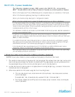
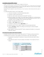
3.  Using the T.A.B. Port, take a reading in IWC.

4.  Using the table below, confi rm the design airfl ow (e.g., 1700 cfm), based on the T.A.B. 

Reading (e.g., 0.19 IWC).

“Example Only”

10. Calibrate M.A.R.V.E.L System 

(for multiple units with a single fan)

NOTE:

 Make sure that the fi lters are in place prior to calibration.

To calibrate the M.A.R.V.E.L. system, follow these steps:

1.  Open the Konsole™ software (see KONTAR-Konsole™ 

Software, page 25 for more 

details).

Close up view of

T.A.B. Port 

Exhaust T.A.B. Readings vs. Airflow

0.00

0.05

0.10

0.15

0.20

0.25

0.30

0.35

800

1050

1300

1550

1800

2050

2300

Airflow (cfm)

T.A.B. Reading (In. WC)

Содержание M.A.R.V.E.L.

Страница 1: ...M A R V E L Model based Automated Regulation of Ventilation Exhaust Levels Operators Manual Installation Operations and Maintenance Instructions PT...

Страница 2: ...al control panel for multiple units with a single fan 13 6 Check pressure transducer 13 7 Calibrate and align IRIS Sensor 14 9 Calibrate the Capture Jet and exhaust air ows 14 10 Calibrate M A R V E L...

Страница 3: ...w adjustment depending on cooking activities Control of common exhaust fan for minimum energy consumption at all times Automatic or on schedule start stops Automatic balancing dampers Early re warning...

Страница 4: ...emperature sensor to measure changes in cooking status Example Differential Pressure Transducer Used in conjunction with the value from the temperature sensor and IR Index to measure and control the a...

Страница 5: ...E L System Components Overview A key feature of the M A R V E L system is exibility It can be applied to a single hood or over multiple hoods depending on the requirements FLOW AIR TS FUSIBLE LINK IR1...

Страница 6: ...it is necessary to start the hood fan in idle mode Used to measure a rapid change in temperature of cooking surfaces for example cooking activities and adjust the air ow in the hood to the required l...

Страница 7: ...temperature dangerously high sensor failed or VFD is in fault NOTE To easily diagnose the alarm use the remote Konsole Diagnostic Software Override push button Used to override pre programmed operatio...

Страница 8: ...rol panel see below is also required Provides permanent Ethernet connection optional Provides temporary Ethernet connection for service Provides RS232 cable connection for on site service Power source...

Страница 9: ...tivity sensed from IRIS sensor s Minimal exhaust ow captures any appliance generated heat Default is 60 of design air ow or as adjusted to meet requirements After idle mode enters Active mode Active M...

Страница 10: ...trol System continuously monitors exhaust air ow at each hood and generates a signal 0 to 10 V proportional to total exhaust air ow as fraction of total design 0 V system is off 7 V system operates at...

Страница 11: ...0 442 5866 or 1 800 4 HALTON If a problem cannot be correct through verbal or written communication with Halton support the system can be connected to the Internet for remote access to Halton engineer...

Страница 12: ...r details 2 Make central control panel connections for multiple units with a single fan Make the following connections at the central control panel a 120 VAC 5 amp power to control panel b Space tempe...

Страница 13: ...e provided by Halton connect each unit to the central control panel This includes Attach the wire to the terminal block in the control panel mounted on the hood 1 Run the wire to the central control p...

Страница 14: ...distance between the sensor and the tool should guarantee the eld of view of the sensor will be completely within the black body surface 5 Register the space temperature t in F 6 Register the IR _Temp...

Страница 15: ...ly 10 Calibrate M A R V E L System for multiple units with a single fan NOTE Make sure that the lters are in place prior to calibration To calibrate the M A R V E L system follow these steps 1 Open th...

Страница 16: ...een Select the Process tab 5 When the calibration is completed con rm that there is a value 0 in the Calibrated_ SP eld NOTE If calibration must be aborted select the Reset_Calibration eld When ready...

Страница 17: ...rature IRT and exhaust air temperature Tex for each hood Calculate and report hood exhaust airflow Q to the exhaust fan controller IRT Tspace dTcook Tex Tex_min Maintain hood exhaust airflow Q Qdesign...

Страница 18: ...plenum door to allow an air jet to protect the sensor optics from contaminants However periodic cleaning may be required to keep the optics clear Gently clean the IRIS socket with isopropyl alcohol o...

Страница 19: ...am for the correct terminations points Remove the face plate of the sensor by removing the 4 face plate screws 2 Lift out the face plate and sensor and gently pull out the sensor wires 3 Remove the se...

Страница 20: ...sconnect the temperature sensor from the terminal block located in the Capture 1 Jet hood Refer to the terminal block diagram on the Halton supplied wiring diagram for the correct terminations points...

Страница 21: ...und the 1 perimeter Remove the actuator cover by removing the 1 screw on the side 2 Disconnect the power to the actuator 3 Record the DIP switch values located in the red holder on the bottom of the a...

Страница 22: ...eplacement actuator Halton Part 16012 Tighten the U bolt on the 7 drive shaft Reset the DIP switches 8 Reset the stop screws 9 Reconnect the power 10 Calibrate the new actuator by pressing the 11 Rese...

Страница 23: ...housing and the exterior metal cover as before 12 Balancing Damper Actuator Removal Replacement To remove the pressure transducer follow these steps Turn off power to transducer 1 Remove covering on p...

Страница 24: ...ove pressure transducer faceplate 4 screws 5 Remove side mount screws 2 screws 6 Replace with Halton Part 18028 7 Reconnect wires and tubing as before Check that the tubing is not kinked 8 5 Remove fa...

Страница 25: ...connection for startup troubleshooting by Halton Technical Support only Temporary cable to laptop connection as required for support RS232 cable connection to laptop pre loaded with KONSOLE software f...

Страница 26: ...59 80 F Appliance ON 80 F Power supply off 220 F NOTE if more than 1 IRIS sensor check each IR_Index value If all values are 220 check that power supply Duct_DP Exhaust fan OFF 0 00 IWC Exhaust fan ON...

Страница 27: ...on CE Alignment Tool does not work Battery low Replace battery Unscrew end of tool remove the battery and replace with same type Exhaust damper blades do not open or close Loose set screws Tighten In...

Страница 28: ...ted with a should be kept readily on hand the amount depending on the number of hoods in the system NOTE Contact Halton for information on other replacement parts as required Part Halton Part Number P...

Страница 29: ...d States Halton Company 101 Industrial Drive Scottsville Kentucky 42164 www haltoncompany com Tel 270 237 5600 Toll Free 800 442 5866 Fax 270 237 5700 Canada Halton Indoor Climate Systems 1021 Brevik...

Страница 30: ...charges miscellaneous tools material charges and labor charges resulting from inaccessibility of equipment will not be paid by Manufacturer This LIMITED WARRANTY SHALL APPLY ONLY to products that hav...

Отзывы: