background image

11

5

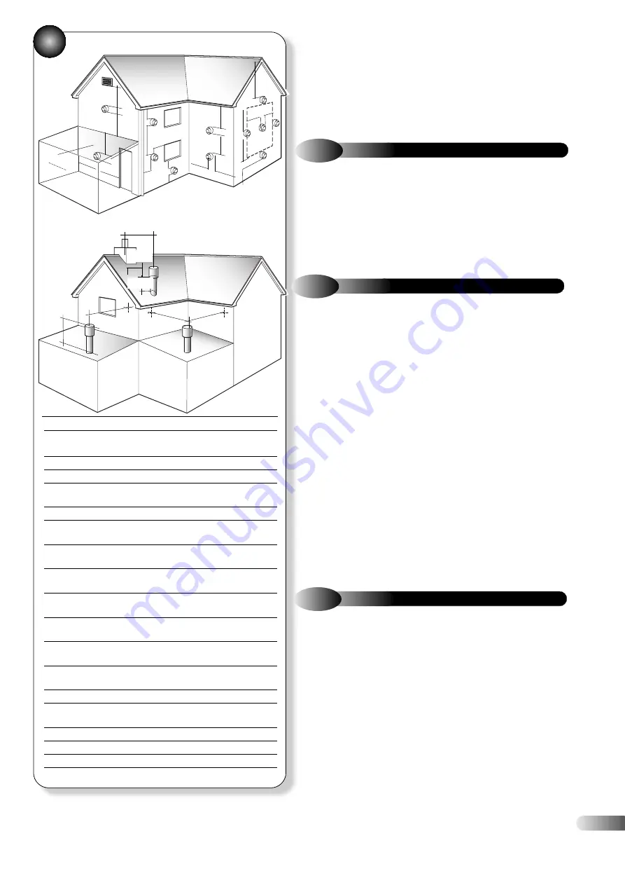
FLUE TERMINAL POSITION

Position Minimum 

spacing

Dir

ectly below an openable window, 

300mm 12in

air vent, or any other ventilation opening

B

Below gutter

, drain/soil pipe

75mm

3in

Below eaves

200mm

8in

D

Below a balcony

200mm

8in

*2500mm 98in

Fr

om vertical drain pipes and soil pipes 150mm

6in

F

Fr

om internal or external corners

300mm 12in

*internal corners

t 1000mm 40in

Above adjacent gr

ound or 

balcony level

300mm 12in 

Fr

om a surface facing the terminal

600mm 24in

t 2500mm 98in

Facing ter

minals

1200mm 48in

*2500mm 98in

Fr

om opening (door/window) in 

1200mm 48in

carport into dwelling

*not recommended

V

ertically from a terminal on the 

1500mm 60in

same wall

Horizontally fr

om a terminal on the 

300mm 12in

same wall

M

Adjacent to opening

300mm 12in

N

Below carpor

t

600mm 24in

*not recommended

O

Fr

om adjacent wall

300mm 12in

P

Fr

om adjacent opening window

1000mm 40in

Q

Fr

om another terminal

600mm 24in

Minimum height

300mm 12in

• •

• •

• •


A

B,C

G

K

M

A

E

F

F

K

B,C

G

G

K

K L

L

J

F

H,I

D,N

C

Q

O

O

P

R

SPECIAL REQUIREMENTS FOR A
VERTICALLY BALANCED FLUE

300mm

Min

430mm

Min

d)

If the appliance is installed in a r

oom or internal space with other

opened flued appliances, then the size of the air vent necessary
should be calculated in accordance with BS 5440-2 Table 2.

e)

Wher

e an open flued system is used, and the flue duct air inlet is

within a compartment then high and low level air vent are necessary
in the compartment, the size of the vents should be calculated in
accordance with BS 5440-2 Table 2.

3.5

CONDENSATE DISPOSAL

The condensate drain connection is suitable for either 21.5 mm or

22 mm plastic push fit or adhesive overflow pipes and fittings. It
should be piped to drain, preferably within the building,
maintaining a continuous 2.5° fall away from the appliance. If the
drain is routed to outside it should be to a drain or soak away,
and any external pipe work should be in 32 mm. Insulation to
protect from freezing in cold weather conditions is also advisable. 

3.6

GAS SUPPLY

a)

The Gas Supplier should be consulted at the installation planning

stage in order to establish the availability of an adequate supply of gas.

b)

An existing ser

vice pipe MUST NOT be used without prior

consultation with the Gas Supplier.

c)

A gas meter can only be connected by the Gas Supplier or by their

contractor.

d)

An existing meter and/or pipe work should be of suf

ficient size to

carry the maximum appliance input plus the demand of any other
installed appliance. (BS 6891: 1988).

A minimum of 22 mm diameter pipe work is

recommended within 1000 mm of the appliance gas cock.
e) Natural gas appliances:

The gover

nor at the meter must give a

constant outlet pressure of 20 mbar (8 in.wg) when all appliances on
the system are running. 

f)

The gas supply line should be pur

ged. WARNING: Before purging

open all doors and windows, also extinguish any cigarettes, pipes, and
any other naked lights.

g)

The complete installation must be tested for gas tightness.

3.7

CENTRAL HEATING SYSTEM

a)

The appliance incorporates all the components necessar

y to

allow them to be connected to a sealed central heating system.
Refer to Figures 9 and 10 for a typical system design, which
incorporates radiators, and a drain facility that must be provided
at the lowest point in the system to allow complete drain down.

b)

The installation should be designed to operate with a flow

temperature of up to 95°C.

c)

A sealed system must only be filled by a competent person.

d)

The available pump head for the appliances ar

e given in

Figure 6. 

* Recommended by the boiler manufacturing industry to prevent
pluming nuisance and damage to buildings.
t Distances can be reduced if plume diverter kit is fitted.

Содержание CLUB HE 18

Страница 1: ...CLUB HE 18 S E A L E D S Y S T E M C O N D E N S I N G B O I L E R 0087 Pin 87 BQ 44 G C Appliance No 41 260 20 Club HE 18 INSTALLATION AND SERVICING INSTRUCTIONS TO BE GIVEN TO THE USER...

Страница 2: ...alve 31 9 4 Fan 32 9 5 Burner 33 9 6 Combustion Chamber Front Insulation 33 9 7 Combustion Chamber Rear Insulation 33 9 8 Heat Exchanger 34 9 9 Pump Head Only 34 9 10 Hydroblock Assembly 35 9 11 Expan...

Страница 3: ...you may be susceptible to irritation High dust levels are usual only if the material is broken Normal handling should not cause discomfort but follow normal good hygiene and wash your hands before ea...

Страница 4: ...e Central Heating Output non condensing 80 60 C Max kW 18 0 Btu h 61500 Min kW 6 0 Btu h 20500 Central Heating Output condensing 50 30 C Max kW 19 7 Btu h 67300 Net kW 18 4 Central Heating Input Max R...

Страница 5: ...Nat Gas 50 30 C 53 CO2 value max rate Nat Gas G20 9 2 0 3 case on 9 0 0 2 case off CO2 value min rate Nat Gas ref only G20 8 6 0 3 CO CO2 Ratio max rate Nat Gas G20 0 0011 0 0014 Flue products mass f...

Страница 6: ...lat roof flashing plate Vertical flue kit Part no 956081 Flue system application Vertical flue kit Part no 956081 Split pipe vertical flue outlet kit Part no 956080 with flat roof flashing plate Raise...

Страница 7: ...6081 2 5 2 KIT B VERTICAL CONCENTRIC FLUE 3b Standard concentric 100 60 vertical flue application Figures 3b 3c through roof attics with a maximum length of 12000mm The kit comprises of the roof termi...

Страница 8: ...In replacement installations the chimney has to be cleared of debris and all flue parts Chimney plate Flexible corrugated plastic flue liner 80mm according to EN 14471 Max length 30m Min length 5m KIT...

Страница 9: ...additional concentric kits are available as optional extras Flue Extension Ducts 1000 mm and 500 mm long each duct extends the flue length by up to 950 mm and 450 mm respectively 93 Extension Elbow Al...

Страница 10: ...ON PLUME DIVERTER TERMINAL INSTALLATION INSTRUCTIONS The diverter allows the terminal clearance to be reduced as follows see diagrams below Clearance H From a surface facing the terminal 600mm Clearan...

Страница 11: ...2 9 APPLIANCE HYDRAULIC CIRCUITS 4 CH MODE 9...

Страница 12: ...UST be protected by a purpose designed K6 terminal guard optional extra Part No 951507 g The air inlet flue outlet MUST NOT be closer than 25 mm 1 in to combustible material h Condensing appliances ha...

Страница 13: ...intaining a continuous 2 5 fall away from the appliance If the drain is routed to outside it should be to a drain or soak away and any external pipe work should be in 32 mm Insulation to protect from...

Страница 14: ...s to obtain the total minimum expansion vessel capacity required in litres PRESSURE GAUGE A pressure gauge is situated on the appliance control panel PRESSURE RELIEF VALVE A pressure relief valve set...

Страница 15: ...nsulated to BS 6500 table 16 3 8 ELECTRICITY SUPPLY 8 S PLAN INSTALLATION TIMED CH DHW FOR FURTHER INFORMATION PLEASE CONTACT HALSTEAD BOILERS LTD SERVICE HELPLINE TEL 01926 834834 The Club HE 18 appl...

Страница 16: ...CONTACT HALSTEAD BOILERS LTD SERVICE HELPLINE TEL 01926 834834 FOR FURTHER INFORMATION PLEASE CONTACT HALSTEAD BOILERS LTD SERVICE HELPLINE TEL 01926 834834 14 9 S PLAN INSTALLATION TIMED CH DHW Y PLA...

Страница 17: ...15 FOR FURTHER INFORMATION PLEASE CONTACT HALSTEAD BOILERS LTD SERVICE HELPLINE TEL 01926 834834 Y PLAN INSTALLATION TIMED CH DHW 11...

Страница 18: ...nsure squareness by hanging a plumb line b Mark the position of the primary wall fixing holes Refer to Figures 12 and 13 c Mark the position of the flue outlet For side flue installation extend the fl...

Страница 19: ...3 SERVICE CONNECTIONS 4 4 CENTRAL HEATING Refer to Figure 15 a Connect the central heating system pipes to the central heating flow and return valves using 22mm pipe work 4 5 GAS CONNECTION Refer to F...

Страница 20: ...no less than 15mm diameter copper pipe to the outlet The pipe outlet should be positioned so that the discharge of water or steam can be noticed but cannot create a hazard to the occupants of the prem...

Страница 21: ...ing to the flue kit instructions and fit to the flue elbow e Fit the flue terminal to the flue system ensuring that the duct joints are not disturbed and that the external sealing ring is seated again...

Страница 22: ...ebris and refill to 0 2 bar above the system design pressure between 0 5 and 1 0 bar by repeating the above procedure Follow the commissioning procedure described below and then repeat this instructio...

Страница 23: ...e test point is 20 1 mbar for natural gas h Check the operation of the programmer or room thermostat if fitted i Turn off the demand from the programmer room thermostat or turn the control knob to the...

Страница 24: ...of very cold conditions the pump may operate and the appliance light for a few minutes to protect the appliance and system from potential frost damage This can only function if the gas and electricity...

Страница 25: ...vertical flue adaptor If suitable equipment to analyse the flue gas is available remove the sampling cap and fit a 6 mm inside diameter sample tube When the appliance is operating at maximum output ch...

Страница 26: ...nect the ignitor plug earth lead and detection plug from the ignitor and detection electrodes e Unscrew the screw holding the gas valve lead plug and disconnect the plug f Disconnect the electrical le...

Страница 27: ...ket b Check that the alignments of the ignition and detection electrodes are correct Refer to Figure 29 Adjust by carefully bending the tip of the electrode rod whilst supporting the base of the rod D...

Страница 28: ...26 INTERNAL WIRING DIAGRAM 7 7 1 FUNCTIONAL FLOW WIRING DIAGRAM 31...

Страница 29: ...lt finding operation involving making or breaking electrical connections always check for EARTH CONTINUITY POLARITY and RESISTANCE TO EARTH Detailed procedures for replacing faulty components are desc...

Страница 30: ...ed which prevents the appliance from firing for 5 minutes Ensure that the control is not in this mode by removing power from the control and restoring it after a delay of 10 seconds RESET LOCK OUT COD...

Страница 31: ...BCC error No flame Incorrect missing BCC Reseat or replace BCC if fitted Check CH flow and return Water flow failure Check pump O Flame for a short period Sensor temperature differential Check no air...

Страница 32: ...the electrical supply leads d Unscrew the two screws holding the ignitor unit remove ignitor unit e Fit the new ignitor unit g Re assemble in reverse order ensure that the ignitor unit is orientated a...

Страница 33: ...d correctly then check for gas soundness 38 36 37 If a new gas valve is fitted it must be adjusted to operate within the quoted CO2 values see Combustion set up table below A suitable calibrated flue...

Страница 34: ...input Case off 8 9 9 1 X measured from valve body 4 3mm to top of screw nominal If the gas control valve is changed then when the appliance is running the flue gas CO2 should be measured refer to sec...

Страница 35: ...otective mask is worn when changing or handling the insulation material Refer to Figure 44 a Ensure supply voltage is isolated and that the gas supply is isolated b Remove the gas control valve fan bu...

Страница 36: ...refer to Figure 46 o Remove the saddle brackets and slide the heat exchanger forwards and out p Re assemble in reverse order check integrity of the flow and return pipe O rings and fibre washers and...

Страница 37: ...is likely that there will still be some water spillage when the Hydroblock is removed a Ensure supply voltage is isolated b Drain down the appliance refer to section 9 19 c Undo the nut holding the m...

Страница 38: ...e sensor to release the bayonet connection and remove from the heat exchanger 9 14 FLUE SENSOR 50 9 15 CONDENSATE DRAIN SYSTEM Refer to Figure 30 a Ensure supply voltage is isolated b Open the drain s...

Страница 39: ...ONTROL PCB Refer to Figures 24 31 and 52 a Ensure supply voltage is isolated b Remove the casing front panel unscrew and lower the control fascia panel c Unplug the electrical leads from the PCB Refer...

Страница 40: ...ot draining the entire CH system close the CH flow and CH return water isolating cocks d Drain down the CH system from the external drain point and drain the boiler using the manual drain tap on the C...

Страница 41: ...Exchanger HE 24 1 451101 9 Pump Head 6 metre 1 500672 10 Hydroblock assembly 1 500651 11 Expansion vessel 1 451020 12 Pressure Relief Valve 1 300734 13 Flow Return temperature thermister 2 500661 14 F...

Страница 42: ...55 1 2 3 4 5 6 7 8 9 10 11 12 13 14 15 16 17 18 19 20 40...

Страница 43: ...Direct Line 01787 475557 Fax 01787 474588 Service Helpline 01926 834834 Training 01926 834838 Email sales halsteadboilers co uk or service halsteadboilers co uk or training halsteadboilers co uk Webs...

Отзывы: