Halstead BFF100 Скачать руководство пользователя страница 26

26

2000225116B

  10  Replacement  of  Parts

IMPORTANT NOTES

REMEMBER, When replacing a part on this appliance, use only
spare parts that you can be assured conform to the safety and
performance specification that we require.  Do not use
reconditioned or copy parts that have not been clearly authorised
by Halstead Boilers Ltd.

Replacement of parts must only be carried out by a competent
person.

Before removing or replacing any parts, turn off the gas supply
at the gas service cock, see diagram 8.2 and isolate the
electrical supply to the appliance.

Unless stated otherwise, all parts are replaced in the reverse
order to removal.

After replacing any parts always test for gas soundness and if
necessary carry out functional check of controls.

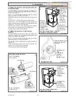
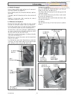
10.1 Electrical Thermistor

Remove front panel to gain access, see section 6.8.

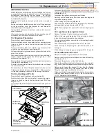
Remove control box cover by undoing the four securing screws
(two on control box, two on the heat shield) and lift off, see
diagram 10.1.

Remove thermistor lead from retaining clip, located on the
control box support bracket, see diagram 8.3.

Release strain relief grommet securing thermistor lead at the
side of control box.

Disconnect the thermistor electrical plug from the control board
(P.C.B) slightly bending back the retaining latch to allow
withdrawal, see diagram 10.2.

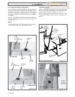
Remove the retaining wire and withdraw the electrical thermistor
from its phial, see diagram 10.3.

Draw the thermistor lead followed by the thermistor out though
the control box case.

Re-assembly note.  When fitting the thermistor make sure it is
fully inserted into the phial, see diagram 10.3.  Take care when
re-threading retaining wire so as not to damage thermistor.

10.2 Control Board (P.C.B)

Remove front panel to gain access, see section 6.8.

Remove control box lid by undoing the four securing screws
(two on control box, two on the heat shield) and lift off, see
diagram 10.1.

Carefully pull the boiler temperature control knob away from the
P.C.B.

CONTROL
BOX
COVER

CONTROL
BOX

SECURING
SCREWS

TERMINAL
BLOCK

Diagram 10.1

9905

ELECTRICAL PLUGS

Diagram 10.2

PCB

Diagram 10.3

PHIAL
POCKET

THERMISTOR

BOILER
TEMPERATURE
CONTROL

Disconnect the electrical  plugs from the control board (PCB)
slightly bending back the retaining latches to allow withdrawal,
see diagram 10.2.

Disconnect the ignition, sensing and earth leads.

Carefully pull the board away from its supports bending back
slightly the retaining latches.

When refitting refer to wiring diagram 9.4.

Take care when replacing the burner temperature control knob
by supporting the potentiometer on the P.C.B.

NOTE: Ensure jumper is in position 'B', refer to wiring diagram
9.4.

10.3  Ignition & Sensing Electrodes

Remove front panel to gain access, see section 6.8.

Refer to the relevant paragraphs of the servicing section to
remove the burner from combustion chamber.

To remove the electrode, unscrew from the retaining bracket,
see diagram 8.12.

Take the electrode out from below and remove the lead.

When removing and replacing the electrode take care not to
damage it.

When refitting, check spark gap, see diagram 8.12,  9.3 and 9.4

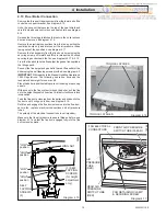
10.4 Multifunctional Control

Remove front panel to gain access, see section 6.8.

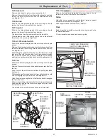
Remove the securing screw and disconnect the electrical plug,
see diagram 10.4.

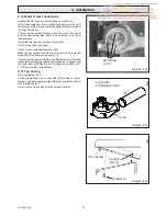
Disconnect the gas cock, on the left hand side.

Support the multifunctional control, remove the four screws (2
long, 2 short) from the flanged connection at the right hand side.

Remove and discard the original “O” ring from the flanged
connection and fit the new “O” ring supplied, into recess, before
fitting the replacement multifunctional control.

After assembly test for gas soundness and purge in accordance
with the current issue of BS6891or in IE, the current edition of
I.S.813 "Domestic Gas Installations".

ELECTRICAL PLUG

Содержание BFF100

Страница 1: ...t of the appliance and must to comply with the current issue of the Gas Safety Installation and Use Regulations be handed to the user on completion of the installation To b e l e f t w i t h t h e u s...

Страница 2: ...provide information on substances hazardous to health Ceramic fibre Insulation Pads Glassyarn These can cause irritation to skin eyes and the respiratory tract If you have a history of skin complaint...

Страница 3: ...atregularintervals Thefrequencyofservicingwilldependupon the particular installation conditions and usage but in general once a year should be enough It is the law that servicing must be carried out...

Страница 4: ...emote control Note If the boiler is turned OFF at the boiler temperature control wait at least 30 seconds before switching on again When the boiler switches off the burner will go out The automatic li...

Страница 5: ...h the rules in force In GB the installation of the boiler must be carried out by a competent person as described in the following regulations The manufacturer s instructions supplied The Gas Safety In...

Страница 6: ...st be correctly earthed polarised and in accordance with the relevant standards In GB this is BS 6891 In IE this is the current edition of I S 813 Domestic Gas Installations Connection of the boiler a...

Страница 7: ...rtment A compartment used to enclose the boiler must be designed and constructed specifically for this purpose An existing cupboard or compartment modified for the purpose may be used Details of essen...

Страница 8: ...unnecessarily high when the central heating pump is off The domestic primary flow and return must be 28mm o d The installation must comply with the current issue of BS5546 and BS6700 see diagram 2 1 I...

Страница 9: ...e roof Care is required to protect the roof if it is made of plastic sheeting If the car port consists of a roof and two or more walls seek advice from the local gas company before installing the boil...

Страница 10: ...optional wall liner kit part no 900862 is available complete with instructions All flue assemblies are designed for internal installation Make sure that the ductings do not slope down towards the boi...

Страница 11: ...screw but do not tighten see diagram 4 5 NOTE The restrictor is fitted to the BFF100 Only Engage the terminal restrictor on the flue terminal by hooking it over the terminal end and engaging the clam...

Страница 12: ...of the remaining lower connections may be used for the gravity domestic hot water return Fit plugs into any unused boiler tappings 4 7 Water Connections Fully Pumped Systems Fit suitable fittings into...

Страница 13: ...ure with retaining wire 4 9 Pipework It is essential that any pipework or fittings do not project more than shown in diagram 4 10 Do not route any pipework water or gas across the front of the combust...

Страница 14: ...ctory with the control box and heat shield fitted in the lower casing height position 9863 SIDE CASINGS FITTING Diagram 4 13 MAX SIDE CASING R H MIN BOILER PLINTH FRONT CASING BRACKET No 8 SCREW 4 LOC...

Страница 15: ...e boiler using the self tapping screws provided see diagram 4 3 IMPORTANT WithregardstotheManualHandlingOperations 1992 Regulations the following operation exceeds the recommended weight for one man l...

Страница 16: ...Make the gas connection to the service cock at the lower left hand side of the boiler see diagram 1 1 The whole of the gas installation including the meter should be inspected tested for soundness and...

Страница 17: ...Make sure the cable is suitably secured When making connections make sure that the earth conductor ismadeofagreaterlength thanthecurrentcarryingconductors so that if the cable is strained the earth c...

Страница 18: ...iagram 6 1 BOILER COMPONENTS 10052 A CONTROL BOX B PHIAL POCKET C GAS SERVICE COCK D BURNER ON NEON E RESET NEON F TEMPERATURE CONTROL G BURNER PRESSURE TEST POINT H GAS PRESSURE ADJUSTMENT SCREW J DA...

Страница 19: ...has lit making sure that all other gas burning appliances and pilot lights are off Gas rate Buckingham 4 BFF100 3 3m3 h 115ft3 h Buckingham 4 BFF115 3 8m3 h 136ft3 h is for guidance only dependent on...

Страница 20: ...te on mains voltage terminals will become live Switch on the electrical supply and gas supply then operate the boiler On completion of the test switch off the electrical supply and gas supply remove a...

Страница 21: ...g back to disengage the retaining lugs then lift up When replacing the flue hood ensure that it rests on the guides and that the rear of flue hood is located under the pegs at the rear and pushed down...

Страница 22: ...levant instructions in sections 8 3 and 8 4 8 3 Burners and Injectors Remove the screws and nuts securing the burner support bracket to the combustion chamber cover see diagram 8 9 Remove the graphite...

Страница 23: ...re calling for heat and circuit water is cold If Reset LED is lit check water system for overheating reset by turning temperature control knob off and on If the LED coding is showing an ignition failu...

Страница 24: ...cause the burner to go out Operationwillnormallyresumeontherestorationoftheelectrical supply Iftheburnerdoesnotrelightafteranelectricalsupplyfailureand theredneononthecontrolpanelislit turntheburnerte...

Страница 25: ...SSURE SWITCH 3 15A FUSE BURNER LIT INDICATOR RESET INDICATOR JUMPER POSITION p bk bk w bk bk b r g bk b LS LIVE Switched N LS N g y g y g y br b b br BROWN b BLUE g y GREEN YELLOW g GREY KEY g y NEUTR...

Страница 26: ...uring screws two on control box two on the heat shield and lift off see diagram 10 1 Carefully pull the boiler temperature control knob away from the P C B CONTROL BOX COVER CONTROL BOX SECURING SCREW...

Страница 27: ...ed with the clear tube from the air pressure switch to the front fan connection as shown in diagram 10 5 and the electricalconnectionsaremadeasshowninwiringdiagram9 4 10 9 Fan Refer to the relevant pa...

Страница 28: ...d the description from the list together with the model name and serial number information from the data label The data label is positioned on the heat shield see diagram 6 1 Key No Part No Descriptio...

Отзывы: