


2
2000225116B
TESTING AND CERTIFICATION
This boiler is tested and certificated for safety and performance. It is therefore important that no alteration is made to the boiler, without
permission, in writing, from Halstead Boilers Ltd.
Any alteration not approved by Halstead Boilers Ltd., could invalidate the certification, boiler warranty and may also infringe the
current issue of the Statutory Requirements, see Section 1.3.
CE MARK
This boiler meets the requirements of Statutory Instrument No. 3083 The boiler (Efficiency) Regulations, and therefore is deemed
to meet the requirements of Directive 92/42/EEC on the efficiency requirements for new hot water boilers fired with liquid or gaseous
fuels.
Type test for purposes of Regulation 5 certified by: Notified body 0086.
Product/production certified by: Notified body 0086.
The CE mark on this appliance shows compliance with:
1. Directive 90/396/EEC on the approximation of the laws of the Member States relating to appliances burning gaseous fuels.
2. Directive 73/23/EEC on the harmonization of the Laws of the Member States relating to the electrical equipment designed
for use within certain voltage limits.
3. Directive 89/336/EEC on the approximation of the Laws of the Member States relating to electromagnetic compatibility.
INFORMATION FOR THE INSTALLER AND SERVICE ENGINEER.
Under Section 6 of The Health and Safety at Work Act 1974, we are required to provide information on substances hazardous to
health.
Ceramic fibre/Insulation Pads, Glassyarn
These can cause irritation to skin, eyes and the respiratory tract. If you have a history of skin complaint you may be susceptible to
irritation. High dust levels are usual only if the material is broken. Normal handling should not cause discomfort, but follow normal
good hygiene and wash your hands before eating, drinking or going to the lavatory. If you do suffer irritation of the eyes or severe
irritation to the skin seek medical attention.
SPARE PARTS
REMEMBER, When replacing a part on this appliance, use only spare parts that you can be assured conform to the safety and
performance specification that we require. Do not use reconditioned or copy parts that have not been clearly authorised by Halstead
Boilers Ltd.
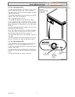
MANUAL HANDLING GUIDANCE
During the appliance installation and the replacement of the heat exchanger it will be necessary to employ caution and assistance
whilst lifting as the appliance or component exceeds the recommended weight for a one man lift.
In certain situations it may be required to use a mechanical handling aid.
Take care to avoid trip hazards, slippery or wet surfaces.
Important Information
Introduction
3
Lighting the Boiler
4
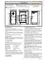
General Data
1
5
Water Systems
2
8
Flue & Ventilation
3
9
Installation
4
10
Electrical Wiring
5
17
Commissioning
6
18
Instructions to User
7
20
Servicing
8
20
Fault Finding
9
23
Replacement Parts
10
26
Spare Parts
11
28
CONTENTS
DESCRIPTION SECTION
PAGE No.
INSTRUCTIONS
FOR USE
INSTALLATION
INSTRUCTIONS
SERVICING
INSTRUCTIONS