


MP5A Operation and Maintenance Manual
________________________________________________________________________________________________________________
Copyright
©
2023
‐
2024
Halogen
Systems,
Inc.
All
rights
reserved
worldwide.
Rev.:
4.02
21
Tools Required:
1.
Philips
#1
Screwdriver
2.
Isopropyl
Alcohol
(if
available)
3.
Lint
free,
clean
cloth
Kit Contents:
1.
Cover
Screws
(x2)
2.
Sensor
Cover
(x1)
3.
Cleaning
Beads
(x2
packs
of
15
ea.)
4.
Impeller
(x1)
5.
Wear
Ring
(x1)
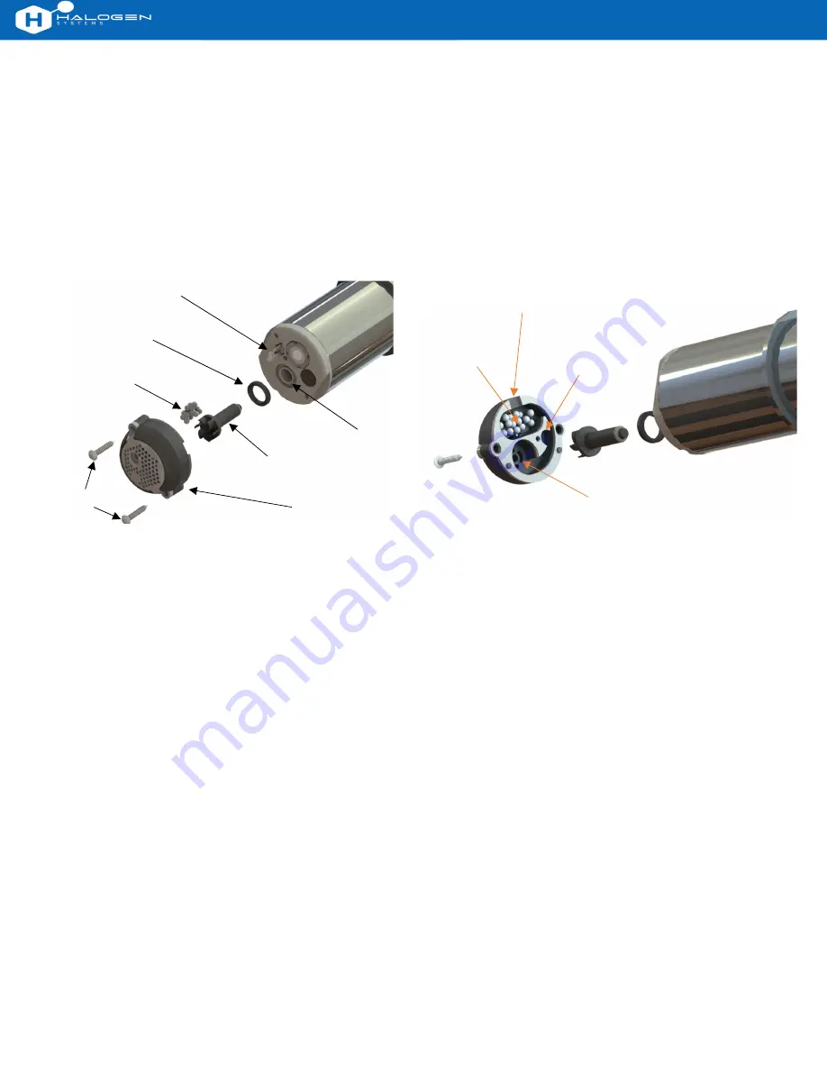
Assembly Overview:
To remove wear parts:
Remove
2x
cover
screws
from
the
sensor
cover.
Maintain
pressure
on
the
sensor
cover
and
rotate
the
sensor
ver cally.
Remove
the
sensor
cover
and
screws
from
the
sensor
end
while
keeping
the
sensor
ver cal.
Remove
the
impeller
from
the
impeller
well.
Impellers
are
magne cally
coupled
and
should
be
removed
easily.
Remove
the
wear
ring.
All
removed
parts
can
be
discarded.
If
fouling
is
present,
it
is
permissible
to
clean
the
sensor
end
with
Isopropyl
Alcohol
and
lint
‐
free
cloth.
Take
care
not
to
scratch
the
electrode
surface.
To install new wear parts:
Remove
parts
from
the
replacement
wear
kit.
Install
new
wear
ring
into
wear
ring
groove.
Install
new
impeller
into
impeller
well.
Place
15
cleaning
beads
into
the
sensor
end
cover
(Figure
2).
Beads
must
only
be
present
in
the
electrode
compartment.
Align
temperature
sensor
and
impeller
with
respec ve
holes
in
sensor
cover.
Lower
sensor
into
sensor
cover.
Twist
the
cover
gently
un l
the
sensor
cover
guide
pins
drop
into
the
sensor
end.
Holding
the
sensor
cover
in
place,
insert,
and
ghten
2x
cover
screws
un l
there
is
no
gap
between
the
sensor
cover
gasket
and
the
sensor
end.
To
prevent
motor
binding,
do
not
over
‐
ghten.
To func on test sensor
:
Power
on
the
sensor
and
verify
that
the
impeller
spins
freely.
If
the
impeller
does
not
spin
freely,
loosen
the
cover
screws
¼
turn
at
a
me
un l
the
impeller
can
be
heard
spinning.
The
sensor
can
also
be
run
in
a
bucket
with
water
to
verify
the
water
stream
from
the
outlet
port.
Temperature
Sensor
Wear
Ring
Cleaning
Beads
x15
Temperature
Sensor
Hole
Electrode
Compartment
Figure
1:
Exploded
assembly
‐
bottom
view.
Figure
2:
Exploded
assembly
‐
correct
cleaning
bead
location.
Outlet
Port
Wear
Ring
Groove
Impeller
Sensor
Cover
Impeller
Bearing
Cover
Screws