SENSITRON
A Halma Company
MT4984
MU+ PK-32
Manual (EN)
P. 44/14
2.8
DETECTORS’ CONNECTION
Gas detectors can be connected to the MU+PK-32 control panel in
two different ways, based on the detector output signal.
I
4-20 mA analogue proportional output (SMART3 NC)
The detector connected to the unit and STG/IN8-PK modules will
send a 4-20 mA signal referring to its range (i.e. 0-300 ppm, 0-30 ppm,
0-100% LEL etc.) and the unit, suitably programmed, will display the rel-
evant gas concentration indication measured by the detector and con-
sequently activate the alarms when the set values are reached.
II
RS485 digital proportional output (SMART P)
The detector connected to the unit will send a data signal on the
RS485 line. This signal is referring to its range (i.e. 0-300 ppm, 0-300
ppm, etc.) and the unit, suitably programmed, will display the relevant
gas concentration indication measured by the detector and conse-
quently activate the alarms when the set values are reached.
-
Detectors with 4-20 mA output
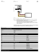
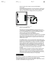
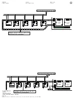
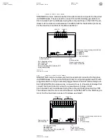
Detectors with 4-20mA analog output are connected to the unit via re-
mote 8-input modules STG/IN8-PK. The modules are connected on
the panel’s bus to be field mounted far from the control panel.
A 4-20mA transmitter requires a 3-core wire for connections: 2 wires
for power supply (usually 12 to 28 Vdc but refer to the gas detector
technical manual) and one wire for the 4-20 mA signal. A 3x0.75 mm2
shielded wire is recommended since it can cover a 100 m distance be-
tween the gas detector and STG/IN8-PK input module.
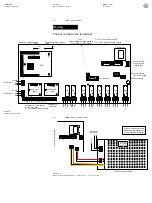
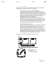
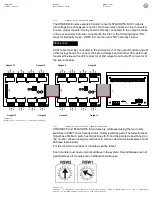
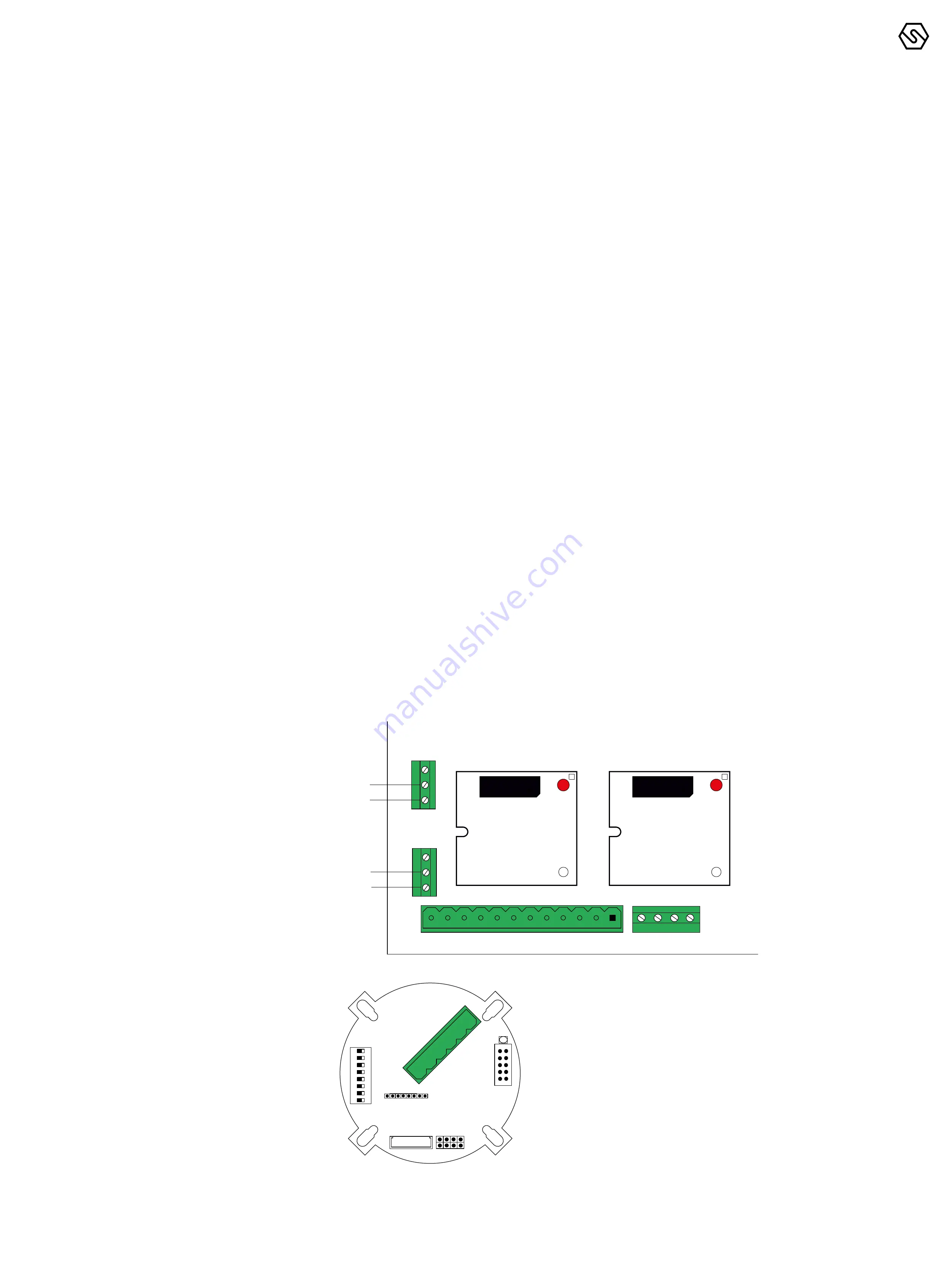
Detectors with 4-20 mA output directly connected to the unit
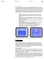
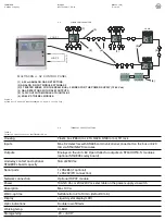
Figure 8
Connection of the
8 detectors to the
control panel
8 analogue 4-20 mA inputs
S: 4-20 mA signal
V+: V+ of detector power supply
V- : V- of detector power supply
+ -
S
B
A
B
A
V- S S S S V+
4 3 2
1
V- S S S S V+
8 7 6
5
1
2
7
6
5
VI+
VI-
VO-
VO+
NC
1
2
7
6
5
VI+
VI-
VO-
VO+
NC

