Intrinsically safe
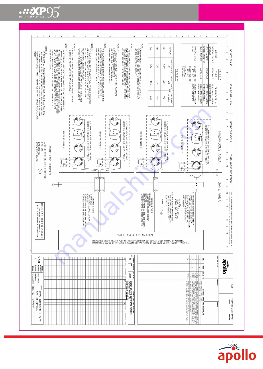
Figure 6: XP95 I.S. System drawing
PP1095/2021/Issue 6
Page 8 of 8
Страница 1: ...s for Ex ia classification In any of these conditions every component must remain cool enough not to ignite the gases for which it is approved Classification of hazardous areas BS EN 60079 10 1 define...
Страница 2: ...ssible configurations of detectors manual call points and safety barriers which are certified by BASEEFA Any user wishing to install a system outside the parameters given on this system diagram cannot...
Страница 3: ...ous area through a voltage and power limiting resistor zener combination similar to a conventional barrier The galvanic isolation technique means that the circuit does not need a high integrity safety...
Страница 4: ...be used A pair contained in a type A or B multicore cable as defined in clause 12 2 2 of BS EN 60079 14 may also be used provided that the peak voltage of any circuit contained within the multicore d...
Страница 5: ...mounting of the base on a flat surface will provide the required degree of protection If the base is mounted on a conduit box e g BESA box or similar whose diameter is less than 85 mm then the base sh...
Страница 6: ...barrier and the total cable capacitance 80nF maximum This should be added to the main fire loop capacitance and compared with the fire panel specification Additionally a galvanic barrier will add 5mA...
Страница 7: ...1 or local codes BS EN 60014 xx and CIE manufacturers recommendation Loop wiring 1 2 3 4 5 6 10 11 12 7 8 9 1 2 3 4 5 6 10 11 12 7 8 9 Ch 1 Ch 2 Functional earth 50mm Minimum 10 11 12 7 8 9 1 2 3 4 5...
Страница 8: ...Intrinsically safe Figure 6 XP95 I S System drawing PP1095 2021 Issue 6 Page 8 of 8...