


Intrinsically safe
PP1095/2021/Issue 6
Page 5 of 8
Safety earth
Shunt zener safety barriers must be connected to a high integrity
earth by at least one and preferably two copper cables, each of
cross sectional area of four mm2 or greater. The connection must
be such that the impedance from the connection point to the main
power system earth is less than one ohm.
Intrinsically safe circuits in the hazardous area should be insulated
from earth and must be capable of withstanding a 500V RMS ac
test voltage for at least one minute. When using armoured or
copper sheathed cables, the armour or sheath is normally isolated
from the safe area busbar.
Remote LED connection
A drive point is provided on each of the XP95 I.S. detectors for
a remote LED indicator. For connection details see Figure 3.
The
indicator must be a standard high-efficiency red LED and does not
require a series limiting resistor since current is limited within
the detector to approximately 1 mA. The remote LED cannot, as
in the standard XP95 range, be controlled independently from the
integral LED since it is effectively connected in series with the
integral LED. The benefit of this configuration is that illumination of
the remote LED does not increase the current drawn from the loop.
The system certification allows for the use of any LED indicator
having a surface area between 20 mm2 and 10 cm2 which
covers all commonly used case styles from T1 (3 mm) upwards
but would exclude some miniature and surface mounted types.
Additional requirements of the certification are that the LED and
its terminations must be afforded a degree of protection of at least
IP20 and must be segregated from other circuits and conductors
as defined in BS EN 60079-14.
The Apollo MiniDisc Remote Indicator (53832-070) is suitable
using connections B(+) and C(-).
Installation
It is important that the XP95 I.S. detectors are installed in such a
way that all terminals and connections are protected to at least
IP20 when the detector is in the base. Special care must be taken
with the rear of the mounting base where live metal parts (rivets)
may be accessible. Flush mounting of the base on a flat surface
will provide the required degree of protection.
If the base is mounted on a conduit box (e.g. BESA box or similar)
whose diameter is less than 85 mm then the base should be fitted
with a XP95 Backplate (Apollo part number 45681-233). Use
of the backplate will prevent access to the metal parts and will
also protect the rear of the base from water ingress. The conduit
box available from Apollo, part no. 45681-204, is also acceptable
for mounting I.S. bases. Apollo also supply a range of deckhead
mounting boxes.
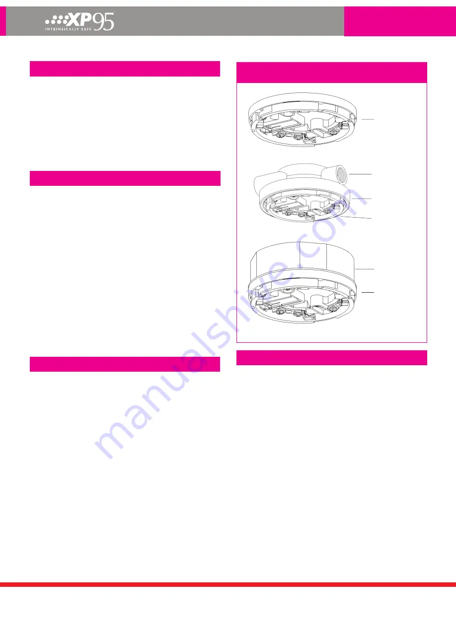
Figure 4 shows permissible methods of installing intrinsically safe
detector bases.
Note:
The earth terminal in the base is provided for convenience
where continuity of a cable sheath or similar is required. It is not
necessary for the correct operation of the detector nor is it provided
as a termination point for a safety earth.
Figure 4: Permissible methods of mounting I.S. detector
bases
Base fitted flush to soffit
I.S. Base
Part No. 45681-215
Base with backplate and BESA box
Standard
BESA box
Backplate
Part No. 45681-233
I.S. Base
Part No. 45681-215
I.S. Base
Part No. 45681-215
Conduit box
Part No. 45681-204
Base fitted to conduit box
Maximum loading of an I.S. circuit
The safety barrier is a mandatory part of an I.S. system, but the
high series impedance limits the number of I.S. detectors that may
be fitted to the circuit. Typically an I.S. circuit will have a maximum
load of about 15 detectors depending on the barrier type, the
type of devices fitted and the number of detector LEDs allowed to
illuminate concurrently by the Control and Indicating Equipment.
When calculating the detector load to ensure the I.S. detection
zone is not overloaded two components of the current drain must
be considered, namely the standing current of the devices by
themselves and the maximum drain caused by alarm LEDs being
illuminated.
The standing current of the devices can be calculated by taking the
sum of the individual device currents on the circuit, as given in the
section ‘Technical data’ for each product.
The maximum number of LEDs that can be illuminated
simultaneously should be limited by the panel software.
Table 5 and Table 6 show the maximum device current which can
be supported for varying numbers of LEDs illuminated for zener
and galvanic barriers respectively.


