


User Manual
ORLocate™
Packing System
© 2010
Haldor Advanced Technologies Ltd
.
P0037 Rev.0
Page 11 out of 28
2.
Set details screen
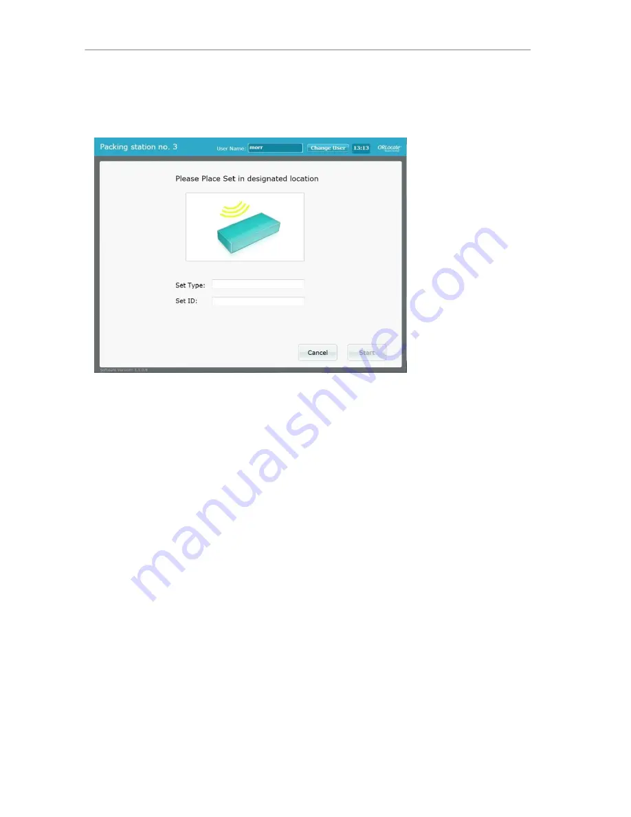
Scan the
Set Tag
in the Tool Pack Antenna Set type and set ID will appear on screen (Figure
4). Ensure set details are correct and select the “Start” button.
Figure 4
3.
Packing main screen
Once the main screen appears (Figure 5) start packing by scanning items according to the
inventory list. The main screen includes 4 areas: On the right side of the screen is the
set
inventory list
. The inventory list includes all items that comprise the set divided to different
areas or levels of packing (as seen in figure 5 “left side, right side”).
The second area of the main screen is the
Set Details area
(top left) in which the set type is
indicated and there is a bar that represents graphically the progress of the assembly.
In the third area of the main screen (middle left) appears the
most recently scanned items
,
and in the forth area of the screen (bottom left) the function buttons are located.