02-1491-00-11.fm
53
Operation
2.3.4
Arm rest control panel
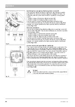
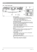
Hako button
The Hako button
switches from transport mode to work mode
or vice versa and starts automated procedures according to the attach-
ment.
The accelerator pedals must be in the neutral position.
In the multifunctional display, the transport mode
Fig. 40-A
, or front tool
carrier symbol
appears.
The vehicle speed is in the:
•
transport mode is 0 to 40 km/h
•
work mode is 16/20/24 km/h according to selected engine speed
You will find the functional description of the Hako button for attachments
in chapter 6.
Joystick
The front tools are operated with the joystick
Fig. 40-70
and the
joystick
.
The joystick
acts on
the
front tool carrier
Fig. 40-12
and on the
hydraulic connections
Fig. 40-11A
.
•
Joystick
forwards: Lowering front tool carrier (floating position)
•
Joystick
back: Raising front tool carrier
•
Joystick
to the left: the left-hand actuator swings to the left
•
Joystick
to the right: the left-hand actuator swings to the right
In the multifunctional display, the upper stop information symbol
or floating position symbol
appears.
The joystick
acts on
the hydraulic connections
Fig. 40-11B
.
•
Joystick
to the left: The right-hand actuator swings to the left
•
Joystick
to the right: The right-hand actuator swings to the right
Turn-push knob
The turn-push knob
Fig. 40-69
is located in the right armrest of the driver's
seat. Menus and submenus are selected in the multifunctional display and
the individual menu item values are set or changed with the turn-push
knob, see page 34.
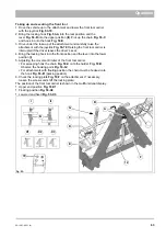
Fig. 40:
C
D
A
B
70
69
72
12
11A
11B
Note
•
For reasons of safety, lowering the front tool carrier with the
vehicle moving is possible only in the work mode. In the
transport mode, the front tool carrier can be lowered only at
a road speed of <5 km/h.
•
If the front tool does not have to be lowered completely,
interrupt the lowering movement by briefly pulling the
joystick back.
•
If the movement of the front tool does not agree with the
movement of the joystick, change over the hydraulic
connections.
Содержание Citymaster 1600
Страница 22: ...22 01 1491 00 12 fm Safety Instructions G A B D E F Fig 3 C F C E C D G A B A...
Страница 26: ...26 02 1491 00 11 fm Operation Fig 5 25 23 16 18 17 19 22 21 20 24 26 27...
Страница 28: ...28 02 1491 00 11 fm Operation Fig 6 28 42 44 41 43 46 47 37 36 38 39 40 35 41 48 49 34 30 32 29 33 31 45...
Страница 30: ...30 02 1491 00 11 fm Operation Fig 7 62 63 61 67 55 50 51 54 53 52 58 57 59 60 65 64 66 68 56...
Страница 32: ...32 02 1491 00 11 fm Operation Fig 8 75 69 78 73 72 79 80 81 82 83 74 77 70 71 76 84...
Страница 85: ...04 1491 00 11 fm 85 Technical Data 4 Technical Data Fig 80 3830 1600 941 1210 975 1964...
Страница 146: ...146 06 1491 00 12 fm Attachments and Options 6 1 5 Technical data Fig 144 2215 4510 1580 2250...
Страница 220: ...220 06 1491 00 12 fm Attachments and Options...


