background image

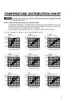
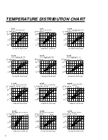
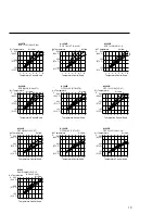
TEMPERATURE DISTRIBUTION CHART

Air flow

2

4

6

8

A1187B

TSOL 18.5×8 (0.73×0.31)

Air flow

2

4

6

8

A1182B

BQFP 24×24 (0.94×0.94)

Air flow

1

2

4 6 8

A1142B

Bent Single 1.5×3 (0.06×0.12)

Air flow

2

4

6
8

A1139B

PLCC 12.5×7.3 (0.49×0.29)
             (18 Pins)

Air flow

2

4

6
8

A1140B

PLCC 11.5×11.5 (0.45×0.45)
             (28 Pins)

Air flow

2

4

6

8

A1141B

PLCC 11.5×14 (0.45×0.55)
             (32 Pins)

Air flow

2

4

6
8

A1136B

PLCC 20×20 (0.78×0.78)
             (52 Pins)

Air flow

2

4

6
8

A1137B

PLCC 25×25 (0.98×0.98)
             (68 Pins)

Air flow

2

4

6
8

A1138B

PLCC 30×30 (1.18×1.18)
             (84 Pins)

Air Temperature 
˚C

500

(932˚F)

300

(572˚F)

100

(212˚F)

Air Temperature
˚C

500

(932˚F)

300

(572˚F)

100

(212˚F)

Air Temperature
˚C

500

(932˚F)

300

(572˚F)

100

(212˚F)

Air Temperature
˚C

500

(932˚F)

300

(572˚F)

100

(212˚F)

Air Temperature
˚C

500

(932˚F)

300

(572˚F)

100

(212˚F)

Air Temperature
˚C

500

(932˚F)

300

(572˚F)

100

(212˚F)

Air Temperature
˚C

500

(932˚F)

300

(572˚F)

100

(212˚F)

Air Temperature
˚C

500

(932˚F)

300

(572˚F)

100

(212˚F)

Air Temperature
˚C

500

(932˚F)

300

(572˚F)

100

(212˚F)

Temperature Control Knob

1

5

8

4

2

7

3

6

Temperature Control Knob

1

5

8

4

2

7

3

6

Temperature Control Knob

1

5

8

4

2

7

3

6

Temperature Control Knob

1

5

8

4

2

7

3

6

Temperature Control Knob

1

5

8

4

2

7

3

6

Temperature Control Knob

1

5

8

4

2

7

3

6

Temperature Control Knob

1

5

8

4

2

7

3

6

Temperature Control Knob

1

5

8

4

2

7

3

6

Temperature Control Knob

1

5

8

4

2

7

3

6

Air Temperature
˚C

500

(932˚F)

300

(572˚F)

100

(212˚F)

Air Temperature
˚C

500

(932˚F)

300

(572˚F)

100

(212˚F)

Air Temperature
˚C

500

(932˚F)

300

(572˚F)

100

(212˚F)

Temperature Control Knob

1

5

8

4

2

7

3

6

Temperature Control Knob

1

5

8

4

2

7

3

6

Temperature Control Knob

1

5

8

4

2

7

3

6

Air flow 2

4

6

8

A1133

SOP 7.5×15 (0.3×0.59)

Air flow 2 4 6

8

A1134

SOP 7.5×18 (0.3×0.7)

Air flow

2

4

6
8

A1135B

PLCC 17.5×17.5 (0.68×0.68)
              (44 Pins)

9

Содержание 850B

Страница 1: ...fore operating the Hakko 850B Keep this manual readily accessible for reference TABLE OF CONTENTS PACKING LIST SPECIFICATIONS 1 SAFETY INSTRUCTIONS 2 PART NAMES 3 PREPARATION ASSEMBLY AND ELECTRICAL C...

Страница 2: ...10V 270W 120V 300W 220V 300W 230V 310W 240V 310W Power Consumption Pump Capacity Control temperature External dimensions Weight 30 W Stand by power consumption 100 120V 2W 220 240V 4W Diaphragm pump 2...

Страница 3: ...personnel or touch the metal parts near the nozzle Do not use the product near combustible gases or flammable materials Advise those in the work area that the unit can reach very high temperatures and...

Страница 4: ...ntrol knob Handpiece holder mounting screw Handpiece holder mounting screw Fuse Handpiece holder Power receptacle Nozzle not included FP pick up with S wire Width of wire 14mm 0 55in FP pick up wire L...

Страница 5: ...l of the station Figure 4 2 Place the handpiece on the holder Figure 5 3 Plug the power cord into a grounded wall socket After connection the automatic blowing function will start sending air through...

Страница 6: ...he thermal protector trip This could damage the unit 2 Place the FP pick up under the IC lead Slip the FP pick up wire under the IC lead Refer to the photo shown If the width of the IC does not match...

Страница 7: ...s with any soldering process however there is always the possibility of forming solder balls bridges between leads and inadequate solder joints Always inspect the finished solder joints for structural...

Страница 8: ...e the heating element B Measure the resistance value Connect an ohmmeter across the connector terminals a The correct values are approxi mately 26 40 100 120V 70 100 220 240V If the resistance value i...

Страница 9: ...4 2 7 3 6 Temperature Control Knob 1 5 8 4 2 7 3 6 Temperature Control Knob 1 5 8 4 2 7 3 6 Temperature Control Knob 1 5 8 4 2 7 3 6 Temperature Control Knob 1 5 8 4 2 7 3 6 500 932 F 300 572 F 100 2...

Страница 10: ...e C 500 932 F 300 572 F 100 212 F Air Temperature C 500 932 F 300 572 F 100 212 F Air Temperature C 500 932 F 300 572 F 100 212 F Air Temperature C 500 932 F 300 572 F 100 212 F Temperature Control Kn...

Страница 11: ...ture C 500 932 F 300 572 F 100 212 F Air Temperature C 500 932 F 300 572 F 100 212 F Temperature Control Knob 1 5 8 4 2 7 3 6 Temperature Control Knob 1 5 8 4 2 7 3 6 Temperature Control Knob 1 5 8 4...

Страница 12: ...84 Pins 19 0 75 19 0 75 24 0 94 24 0 94 29 1 14 29 1 14 6 9 0 27 6 9 0 27 A 21 0 83 B 21 0 83 A 26 1 02 B 26 1 02 A 31 1 22 B 31 1 22 A 9 0 35 B 14 0 55 A1140B PLCC 11 5 11 5 0 45 0 45 28 Pins A1141B...

Страница 13: ...e description Screws must be ordered separately Item No 1 2 3 4 5 6 7 8 Part No B2544 A1143 A1144 A1145 A1146 B1188 B1441 B2556 B1354 B2634 B2635 Part Name Handle Heating element Heating element Heati...

Страница 14: ...2424 B2425 B2426 B2436 Part Name Cover Handpiece holder Sound proof tank Air pump Air pump Air pump Silicone tube Fuse Fuse Power receptacle Chassis Radiation sheet P W B P W B P W B P W B Switch Air...

Страница 15: ......

Отзывы: