


A. Broken Heating Element/Sensor
●
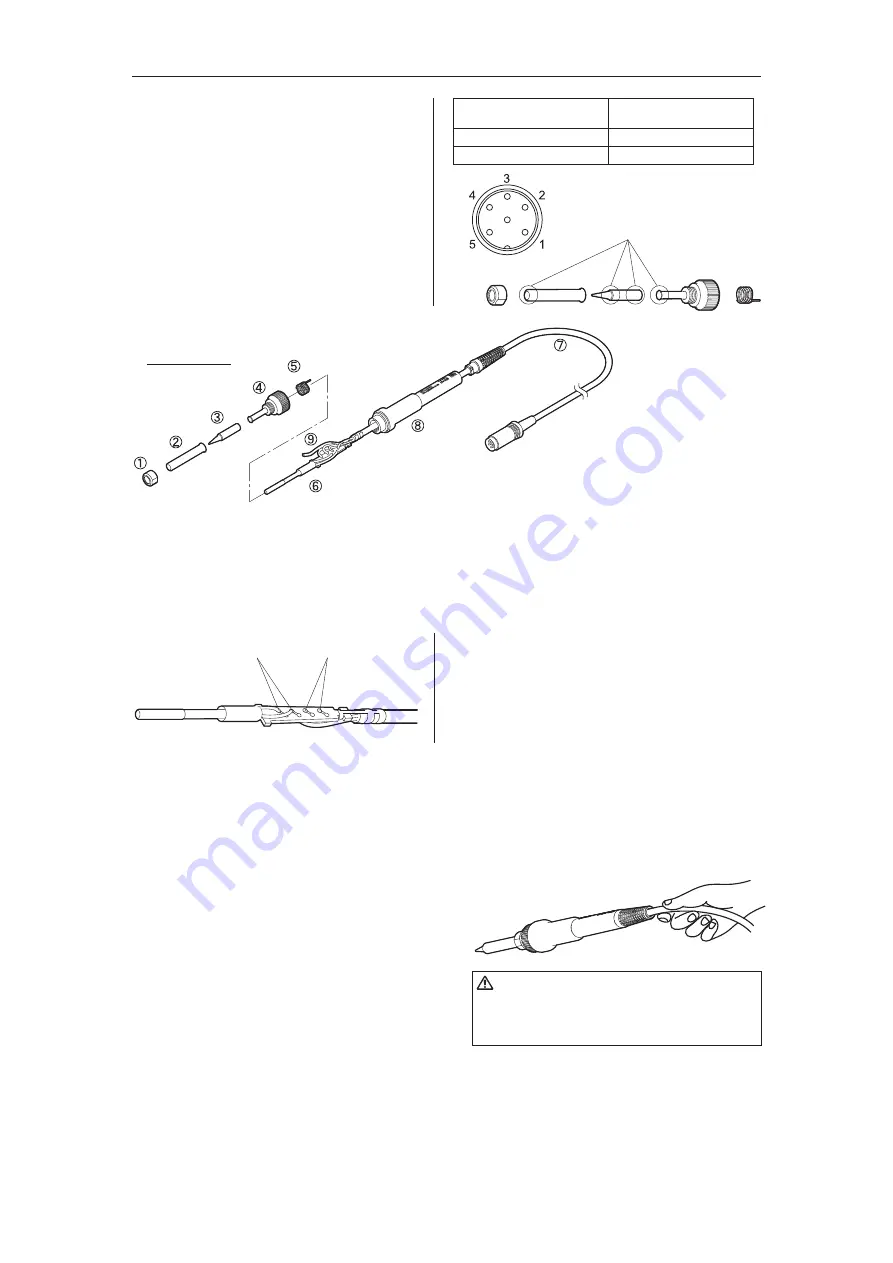
Disassembling
a. Between pins 4 & 5
(Heating Element)
b. Between pins 1 & 2 (sensor)
c. Between pin 3 & Tip
2.5 – 3.5 Ω
(at time of room temperature)
43 – 58 Ω
2 Ω or less
Heating element
resistance (red)
Sensor resistance
(blue)
8. CHECKING PROCEDURE
Buff lightly.
Disconnect the plug of the cord assembly and
measure the resistance value between the ping
of the connecting plug as follows.
If the values of “a” and “b” are outside the value
in the table, replace the heating element
(sensor) and/or cord assembly.
If the value of “c” is over the value in the table,
remove the oxidization film by lightly rubbing with
sand-paper or steel wool the points shown in the
drawing on the right.
After replacement
1. Measure the resistance between pins 4 and 1, 4 and 2, 5 and 1, and 5 and 2. If it is not ∞, the heating
element and sensor are touching. This will damage the circuit board.
2. Measure the resitance “a,” “b,” and “c” to confirm that the leads are not twisted and that the grounding
spring is properly connected.
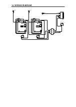
B. Broken Cord Assembly
There are two methods of testing the cord
assembly.
1. Turn the unit ON and set the temperature control
knob to 480℃. Then bend the iron cord at various
locations along its length, including in the strain
relief area. The cord assembly needs to be
replaced if S-E is displayed or although the LED
heater lamp flashes, the tip temperature doesn’t
rise.
2. Check the resistance between the plug pin and the
terminal lead.
Pin 1: Red Pin 2: Blue Pin 3: Green Pin 4: White
Pin 5: Black
Resistance: 0 Ω.
If it is higher than 0 Ω or is ∞, the cord should be
replaced.
CAUTION
The power lamp starts to flash when the
temperature reaches 480°C (880°F) regardless
of the condition of the cord.
1. Turn the nut
①
counterclockwise and remove the
tip enclosure
②
and the tip
③
.
2. Turn the nipple
④
counterclockwise and remove it
from the iron.
3. Pull both the heaing element
⑥
and the cord
assembly
⑦
out of the handle
⑧
. (Toward the tip of
the iron).
4. Pull the grounding spring
⑤
out of the sleeve of the
terminal
⑨
.
* Measure when the heating element is at room
temperature.
1. Heating element resistance (red) 2.5 – 3.5 Ω
2. Sensor resistance (blue) 43 – 58 Ω
If the resistance value is not normal, replace the
heating element. (Refer to the instructions included
with the replacement part.)


