Hakko Electronics FP-101 Скачать руководство пользователя страница 9

 Checking Procedure

WARNING:

Unless otherwise directed, carry out these procedures with the power switch OFF and the power UNPLUGGED.

Check for a broken heater or
sensor

1. Check for a broken heater or sensor

Measure the resistance
across this position.

1Y100CB3

T7-D24

Verify the electrical integrity of the heater and
sensor.
Measure the resistance of the heater and
sensor while at room temperature (15 to 25

°

C;

59 to 77

°

F). It should be 8

Ω ±

10%. If the

resistance exceeds these limits, replace the tip.

Check the grounding line

1. Unplug the connection cord from the station.
2. Measure the resistance value between Pin 2

and the tip.

3. If the value exceeds 2

 (at room temperature),

perform the tip maintenance described on P.12.
If the value still does not decrease, check the
connection cord for breakage.

 Checking the connection cord

for breakage

1. Remove the soldering tip and the sleeve

assembly.

2. Turn the front piece of the FM-2021 clockwise

and remove the cover.

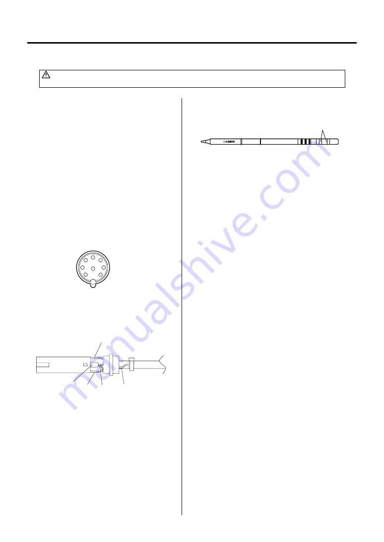
3. Measure the resistance values between the

connector and the lead wires at the socket as
follows:

Pin 1 – Red

Pin 2 – Green

Pin 3 – Black

Pin 5 – White

If any value exceeds 0

, replace the FM-2021.

Black

Green Red White Blue

1

4

7

2

8

5

6

3

8

Содержание FP-101

Страница 1: ...ntrol features unique to the FP 101 make it applicable to a broad range of soldering applications Please read this manual before operating the FP 101 Keep this manual readily accessible for reference...

Страница 2: ...nt panel indicate the heat range selected for the FP 101 6 5 650 F 343 C 7 0 700 F 371 C 7 5 750 F 399 C 8 0 800 F 427 C 9 F 5 C at idle temperature Power consumption Tip to ground resistance Tip to g...

Страница 3: ...o become wet or use it with wet hands Do not modify the FP 101 Use only genuine Hakko replacement parts Do not bend or damage the control card If the card does become damaged do not force the card int...

Страница 4: ...n Tip tray Tip cleaner Tip not included Receptacle Card slot The heat range selector button Auto power shutoff switch on the bottom front of the case FM 2021 Connector assembly Sleeve assembly 7 5 6 5...

Страница 5: ...pad 4 Soldering station 1 Insert the connector cord into the receptacle at the front of the station 2 Plug the power cord into a grounded wall socket The FP 101 is protected against electrostatic dis...

Страница 6: ...F 343 C 7 0 700 F 371 C 7 5 750 F 399 C 8 0 800 F 427 C The ranges are approximate values only the actual tip temperature depends upon tip geometry and mass These lights are indicators one must press...

Страница 7: ...ed with solder turn the wire until a clean surface is presented When changing the cleaning wire lift the case top vertically to prevent solder debris from falling out 7 PARAMETER SETTINGS Auto power s...

Страница 8: ...s not active Never allow the unit to idle at a high temperature for extended periods This will allow the tip to become oxidized Turn the power switch OFF If it is to be out of service for several hour...

Страница 9: ...Check the grounding line 1 Unplug the connection cord from the station 2 Measure the resistance value between Pin 2 and the tip 3 If the value exceeds 2 at room temperature perform the tip maintenanc...

Страница 10: ...e heat range indicator lamp will blink rapidly and the heater is shut down NOTE Only the FM 2021 is compatible with the FP 101 Heater terminal short circuit error Soldering iron error 7 5 6 5 8 0 7 0...

Страница 11: ...eakage Solder does not wet the tip CHECK Is the tip contaminated with oxide ACTION Remove the oxide see Tip maintenance on P 7 The tip temperature is too high CHECK Is the connection cord broken ACTIO...

Страница 12: ...iring board for switch Grounding plate Fuse Description with LED lens and shieding plate 120V with rubber foot 2A UL 2 1 3 3 5 4 9 8 7 6 Tapping screw 4 12 4 Tapping screw 3 12 1 Tapping screw 3 8 3 T...

Страница 13: ...rt Name Conversion kit Connector assembly Connector cover Sleeve assembly Sleeve assembly Sleeve assembly Tip Heat resistant pad Specifications is yellow Yellow Orange Blue Iron Holder 1 B2790 B2791 B...

Страница 14: ...3 0 1 6 7 5 3 0 R0 2 9 3 R0 2 7 9 T7 JL02 SHAPE 0 2RLB Bent T7 JS02 SHAPE 0 2RSSB Bent 0 37 0 31 60 12 1 T7 C1 SHAPE 1C Bevel 0 47 0 04 45 1 11 5 T7 BC1 SHAPE 1BC Bevel 0 45 0 04 1 45 11 5 T7 BCF1 SH...

Страница 15: ...12 19 5 0 77 20 9 0 82 0 4 T7 1008 SOP19 5 x 10 2 20 5 4 3 13 4 6 0 24 0 17 0 53 14 8 0 58 0 81 T7 1009 SOP13 4 x 20 5 14 8 9 7 5 5 13 6 0 54 8 5 0 33 0 22 0 38 0 58 T7 1201 PLCC13 6 x 8 5 11 5 11 5 5...

Страница 16: ...DUCTS INC 28920 N AVENUE WILLIAMS VALENCIA CA 91355 U S A TEL 661 294 0090 FAX 661 294 0096 Toll Free 800 88 HAKKO www hakkousa com 4 2 5 5 6 Sep 2003 MA01226JU030930 13 WIRING DIAGRAM AC TR RED BLK W...

Отзывы: