17
connector
at the rear of the HDTV.
3. Turn on the HDTV and VCR.
4. Select ATV/DTV using the SOURCE button
on the remote control or the control key
on the side of the TV.
NOTE:
If you have an off-air antenna or cable TV,
connect it to the “Antenna In” connector
on the rear of your VCR.
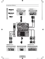
Connecting Your HDTV Set-Top Box
Using HDMI (19”/22” only have one
HDMI)
HDTV Set-Top Boxes that have a HDMI digital
interface should be connected to the HDMI
input of the LCD HDTV
for optimal results.
Connecting your HDTV Set-Top Box
(Best)
1. Turn off the HDTV and HDTV Set-Top
Box.
2. Connect a HDMI cable to the HDMI
output of your HDTV Set-Top Box and the
other end to the HDMI Input at the
rear
of the HDTV.
3. Turn on the HDTV and HDTV Set-Top
Box.
4. Select HDMI using the SOURCE button on
the remote, side of the HDTV, or directly
by pressing the HDMI button
on the
Remote Control.
NOTE:
The HDMI input on the HDTV supports
High-bandwidth Digital Content Protection
(HDCP). HDCP encrypts
the transmission
between the video source and the digital
display for added security and protection.
Refer to your HDTV Set-Top Box user
manual for more information about the
video output requirements of the
product
or consult your cable or satellite operator.
For HDTV Set-Top Boxes with DVI
1. Turn off the HDTV and HDTV Set-Top
Box.
2. Using a HDMI-DVI cable, connect the DVI
end to your HDTV Set-Top Box and the
HDMI end to the HDMI Input at
the rear
of the HDTV.
3. Turn on the HDTV and HDTV Set-Top
Box.
4. Select HDMI using the SOURCE button on
the remote, side of the HDTV, or directly
by pressing the HDMI button
on the
Remote Control.
NOTE:
The HDMI input on the HDTV supports
High-bandwidth Digital Content Protection
(HDCP). HDCP encrypts
the transmission
between the video source and the digital
display for added security and protection.
Refer to your HDTV Set-Top Box user
manual for more information about the
video output requirements of the
product
or consult your cable or satellite operator.
The DVI to HDMI connection provides
video only. Connection to an alternate
audio player is required for audio.
Содержание LT19A1
Страница 28: ...28 4 Mechanical Instructions 1 Remove the 4 screws to remove stand 2 Remove the 7 screws to remove rear cover ...
Страница 34: ...34 6 PCB Layout 6 1 Main Board 715G3693M01000004K ...
Страница 35: ...35 ...
Страница 36: ...36 6 2 Power Board 715G2783 2 7 ...
Страница 37: ...37 ...
Страница 38: ...38 ...
Страница 39: ...39 6 3 Key Board 715G3303K01001004S 6 4 IR Board 715G3870R01000004M ...
Страница 41: ...41 8 Block Diagram ...
Страница 63: ...63 11 Exploded View ...