background image

5

5

4

4

3

3

2

2

1

1

D

D

C

C

B

B

A

A

5

V

stb

BL-AD

J

U

S

T

+

12V

LED

9

ON

/B

K

DB

LED

1

1

LED

1

0

LED

1

2

LED

1

3

LED

1

4

LED

1

5

LED

1

6

BL-AD

J

U

S

T

+5
V

S

HD

5

V

stb

ON

/B

K

ON

/B

K

S

HD

LED

1

OVP

LED

2

LED

3

S

HD

LED

1

LED

4

OVP

LED

3

FB

LED

5

FB

LED

2

LED

+

LED

6

LED

4

LED

7

LED

5

LED

7

LED

8

LED

6

LED

+

DRV

LED

8

DRV

+5
V

PW

R

-O

N

/O

F

F

BL-AD

J

U

S

T

LED

11

LED

14

LED

10

LED

13

LED

9

LED

16

LED

12

LED

1

5

LED

1

LED

2

LED

6

LED

5

LED

+

LED

+

LED

4

LED

3

LED

8

LED

7

12VA

FB

FB
1

LED

+

LED

14

LED

13

LED

12

LED

11

LED

9

LED

10

LED

16

LED

15

LED

+

PW

R

-ON

/O

F

F

5VA

BL-AD

J

U

S

T

ON

/B

K

DB

BX

BX

5

V

stb

+

12VB

+

12VB

+

12V

+1
2

V

+

12V

FB
1

LED

6

LED

5

LED

4

LED

3

LED

1

LED

2

LED

8

LED

7

LED

+

LED

+

LED

4

LED

8

LED

7

LED

6

LED

5

LED

1

LED

2

LED

3

LED

1

LED

3

LED

+

LED

5

LED

7

5

V

stb

12VA

12VA

ON

/B

K

BL-AD

J

U

S

T

+5
V

+

12VB

+5
V

+

3

.3

V

stb

5VA

12VA

+5
V

12VA

5VA

5VA

PW

R

-O

N

/O

F

F

2

O

N

_PBAC

K

2

A

D

J

-PW

M

2

5

V

stb

2

Ti

tle

S

iz

e

D

oc
um

ent

 N
u

m

ber

R

e

v

D

a

te

:

S

heet

of

PO

W
E

R

1.

0

MS

D

33

91D

S

Cu
s

to

m

99

Fr
id

a

y

, Apri

l 06,

 2012

Ti

tle

S

iz

e

D

oc
um

ent

 N
u

m

ber

R

e

v

D

a

te

:

S

heet

of

PO

W
E

R

1.

0

MS

D

33

91D

S

Cu
s

to

m

99

Fr
id

a

y

, Apri

l 06,

 2012

Ti

tle

S

iz

e

D

oc
um

ent

 N
u

m

ber

R

e

v

D

a

te

:

S

heet

of

PO

W
E

R

1.

0

MS

D

33

91D

S

Cu
s

to

m

99

Fr
id

a

y

, Apri

l 06,

 2012

1  CN2 

7P

18.5

E

21.6 U3    U4

"

D10

"

2  CN805  CN806 

7P

26",CN2

"

3  CN804  

7P

23.6, U4

"

LED

H:ON

L:OFF

\7

CN2

FG

18.5

24

\7

U5

G9`>\7

U5+U3

26

\7

R850

G\7

FG

G

F".W

26

\7

0R

G

I

OFF

ON

L:ON

H:OFF

R41 only for 3.3V PWM output

Note: Left C47 NC, R38 change to 100ohm if want to output PWM puls

XY

 !

I

"

G

#$

EMC

%

I

&

Vout=1.25

×

!

R826+R823

/

/R826

?

'

.W

(

R826

G

)

R823

G

*+,-./01

N

Iout=1.194

×

400/(R828//R829)

Iout=1.194

×

400/(R841//R842)

J

3X/4X

23

XY

----

456

R7
0

22

Ω

-1206

R7
0

22

Ω

-1206

D

801

F

L

Z

18VC

D

801

F

L

Z

18VC

R

750

47R R

750

47R

J7

FO

R

 C
P

T

J7

FO

R

 C
P

T

1

2

C

1

6

1uF

C

1

6

1uF

C

O

N

810

C

O

N

810

1

2

3

4

5

6

+

EC

806

220uF

/16V

+

EC

806

220uF

/16V

D

803

2A06

D

803

2A06

R

841

12K

R

841

12K

C3
8

1uF

C3
8

1uF

C

1068

1000p/

25V

C

1068

1000p/

25V

C3
9

100pF

C3
9

100pF

R

853

100R

R

853

100R

U4

AP3608E

U4

AP3608E

CH2

2

CH1

1

CH3

3

CH5

7

CH4

4

P

G

ND1

5

P

G

ND2

6

CH6

8

CH7

9

CH8

10

PW

M

11

NC

12

FB

X

13

I

S

ET

14

FB

15

S

DB

16

S

DB

X

17

AG

N

D

18

VC

C

19

EN

20

C

Y802

2.

2nF

C

Y802

2.

2nF

D9

S

R

360 D

O

-15

D9

S

R

360 D

O

-15

2

1

C1
7

10nF

/25V

C1
7

10nF

/25V

C

1040

0.

1uF

C

1040

0.

1uF

R

959

1k

R

959

1k

+

EC

4

220uF

/16V

+

EC

4

220uF

/16V

1

2

J4J4

1

2

3

4

R

886

NC/

2

4

K

R

886

NC/

2

4

K

R

828

12K

R

828

12K

R

900

1K

R

900

1K

R

839

3.

3K

R

839

3.

3K

C

1041

22nF

/25V

C

1041

22nF

/25V

C2
6

1000P/

50V

C2
6

1000P/

50V

R

867

22R

/1206

R

867

22R

/1206

C3
2

10nF

/25V

C3
2

10nF

/25V

R3
5

30K

R3
5

30K

D

806

S

BR

20100

T

O

-220B

D

806

S

BR

20100

T

O

-220B

2

2

1

1

3

3

R3
4

200K

R3
4

200K

10uH

/3

.8

A

L806

10uH

/3

.8

A

L806

Q809

AO4468

Q809

AO4468

4

2

1

3

8

6

5

7

C1
8

0.

1uF

C1
8

0.

1uF

U

809

T

L431

U

809

T

L431

R

848

NC

R

848

NC

MP2303

U2

R

T

8296A

MP2303

U2

R

T

8296A

VI
N

2

S

W

3

GND

4

FB

5

ON

/O

F

F

7

COMP

6

B

S

1

NC/

SS

8

GN

D

9

J

R

2
0

R

-1206

J

R

2
0

R

-1206

R

832

100R

R

832

100R

R

720

20K

R

720

20K

D

811

FR1

0

7

D

811

FR1

0

7

R3
2

7.

5K/

0603

R3
2

7.

5K/

0603

R

895

1R
-1206

R

895

1R
-1206

R

899

36K

R

899

36K

+

EC

3

220uF

/25V

+

EC

3

220uF

/25V

1

2

D

807

2A06

D

807

2A06

R

849

NC

R

849

NC

C

1061

0.

1uF

C

1061

0.

1uF

R8
7

7

470k

R8
7

7

470k

R

901

100K

R

901

100K

C

Y

800

C

Y

800

R

700

22R R

700

22R

R

878

470k

R

878

470k

D

809

F

R

107

D

809

F

R

107

R

826

1.

5K

R

826

1.

5K

C2
3

100P/

50V

C2
3

100P/

50V

C2
0

0.

1uF

C2
0

0.

1uF

R

957

1k

R

957

1k

TP
5

TP
5

C

931

0.

1uF

/50V

C

931

0.

1uF

/50V

R

953

1K

R

953

1K

R

956

1k

R

956

1k

R

823

51K

R

823

51K

R

903

2R
2-1206

R

903

2R
2-1206

C

1063

0.

1uF

C

1063

0.

1uF

Q812

3904

Q812

3904

1

2

3

R

846

NC

R

846

NC

C

1

5

1uF

C

1

5

1uF

R1
8

270K R1

8

270K

R7
6

100R

R7
6

100R

R

869

22R

/1206

R

869

22R

/1206

+

EC

805

47uF

/400V

+

EC

805

47uF

/400V

C

1022

680PF

C

1022

680PF

CN2

H

EAD

ER

 2

CN2

H

EAD

ER

 2

3

3

4

4

1

1

2

2

R

844

200K

R

844

200K

R

884

1M

R

884

1M

C

1071

0.

1uF

C

1071

0.

1uF

D

804

2A06

D

804

2A06

R

891

1K

R

891

1K

NP2

NP1

NB1

NB2

NP2

T

103

EF
D

2

5

NP2

NP1

NB1

NB2

NP2

T

103

EF
D

2

5

12V

8

GN

D

10

12V

7

GN

D

9

11

5V

3

3

2

2

1

1

6

6

5

5

5V

12

4

4

R

876

470K

R

876

470K

R8
2

9

NC

R8
2

9

NC

R

888

1M

R

888

1M

R

2297

10K

R

2297

10K

R2
7

100K

R2
7

100K

R

865

68K/

2W

R

865

68K/

2W

R

831

51K

R

831

51K

R6
5

0

.6

8

Ω

-0805

R6
5

0

.6

8

Ω

-0805

D810

HER207

D810

HER207

R

847

NC

R

847

NC

Q810

10N

6

0

Q810

10N

60

2

3

1

C

1037

680PF

C

1037

680PF

R

955

4.

7K

R

955

4.

7K

R

893

470R

R

893

470R

J

R

1
0

R

-1206

J

R

1
0

R

-1206

R

856

1R
-1206

R

856

1R
-1206

C3
5

NC C3

5

NC

TP
2

TP
2

R

952

100R

R

952

100R

C

001

101/

1KV

C

001

101/

1KV

R

896

2R
2-1206

R

896

2R
2-1206

Q806

AO4435

Q806

AO4435

C3
1

1000P/

25V

C3
1

1000P/

25V

C2
5

0.

1

μ

F

/25V

C2
5

0.

1

μ

F

/25V

R

883

1M

R

883

1M

LF
801

LF
801

3

4

1

2

C

N

803

FO

R CP

T

C

N

803

FO

R CP

T

1

2

3

4

5

6

7

8

9

10

FB7
40R

FB7
40R

C

1034

472/

1KV

C

1034

472/

1KV

R

881

1M

/1206

R

881

1M

/1206

R

8

92

22R

-0805

R

8

92

22R

-0805

+

C

1035

470uF

/16V

+

C

1035

470uF

/16V

C4
0

100pF

C4
0

100pF

R2
6

N

C

/200R

R2
6

N

C

/200R

L807

N

C

/10uH

/3

.8

A

L807

N

C

/10uH

/3

.8

A

RV

1

PT
C

R

D

H

5-3A-W

RV

1

PT
C

R

D

H

5-3A-W

U

808

PC

817

U

808

PC

817

1

2

4

3

C

N

802

FO

R CP

T

C

N

802

FO

R CP

T

1

2

3

4

5

6

7

8

9

10

C

N

804

H

EAD

ER

 12

C

N

804

H

EAD

ER

 12

1

2

3

4

5

6

7

8

9

10

11

12

R6
9

0

.6

8

Ω

-0805

R6
9

0

.6

8

Ω

-0805

R

845

20K

R

845

20K

F

800

F

800

R3
6

5.

6K 1%

R3
6

5.

6K 1%

R

890

10K

R

890

10K

C

N

800

A

C

 IN

C

N

800

A

C

 IN

1

2

R8
4

2

NC

R8
4

2

NC

J8J8

1

2

Q811

3906

Q811

3906

C

Y801

C

Y801

R6
8

0

.6

8

Ω

-0805

R6
8

0

.6

8

Ω

-0805

C

1070

2.

2uF

C

1070

2.

2uF

R1
4

100R

R1
4

100R

J1

FO

R

 C
P

T

J1

FO

R

 C
P

T

1

2

3

4

5

6

R

958

N

C

/22K

R

958

N

C

/22K

C2
2

3.

3nF

/25V

C2
2

3.

3nF

/25V

R

898

1K

R

898

1K

C

950

10uF

C

950

10uF

+

C

1053

47uF

/50V

+

C

1053

47uF

/50V

L2

15uH

-3A

L2

15uH

-3A

+

C

1026

47uF

/50V

+

C

1026

47uF

/50V

R

902

10K

R

902

10K

C

750

100pF

C

750

100pF

+

C

1039

1000uF

/25V

+

C

1039

1000uF

/25V

C1
0

5

6

0.

1uF

/50V C1

0

5

6

0.

1uF

/50V

TP
4

TP
4

R

850

100R

R

850

100R

Q103

B601001

T

O252-

D

PAK

Q103

B601001

T

O252-

D

PAK

R3
1

47K

R3
1

47K

Q808

3904

Q808

3904

R8
3

7

NC

R8
3

7

NC

D

805

2A06

D

805

2A06

R

870

100K

R

870

100K

D1
0

S

R

360 D

O

-15

D1
0

S

R

360 D

O

-15

2

1

C2
4

0.

1

μ

F

/25V

C2
4

0.

1

μ

F

/25V

U3

AP3608E

U3

AP3608E

CH2

2

CH1

1

CH3

3

CH5

7

CH4

4

PG

N

D

1

5

PG

N

D

2

6

CH6

8

CH7

9

CH8

10

PW

M

11

NC

12

FB

X

13

I

S

ET

14

FB

15

S

DB

16

S

DB

X

17

AG

N

D

18

VC

C

19

EN

20

C

951

1uF

C

951

1uF

+

EC

5

220uF

/16V

+

EC

5

220uF

/16V

1

2

D4

SS

24

D4

SS

24

2

1

TP
3

TP
3

R

951

4.

7K

R

951

4.

7K

R

885

1M

R

885

1M

TP
1

TP
1

C

1038

0.

1uF

C

1038

0.

1uF

C3
7

100pF

C3
7

100pF

NP2

NP1

NB1

NB2

NP2

T

102

EF
D

2

5

NP2

NP1

NB1

NB2

NP2

T

102

EF
D

2

5

12V

6

GN

D

4

12V

7

GN

D

5

3

5V

10

10

NC

11

12

12

8

8

9

9

5V

2

NC

1

R

889

100R

R

889

100R

R

834

NC

R

834

NC

J3J3

1

2

R

894

470R

R

894

470R

+

C

1021

47uF

/50V

+

C

1021

47uF

/50V

R

954

N

C

/10K

R

954

N

C

/10K

R

875

10k R

875

10k

R

830

20K

R

830

20K

R

835

NC

R

835

NC

U

807

U

807

GND

1

RI

3

C

S

4

VDD

5

GA

T

E

6

FB

2

RT1RT1

R

721

10K

R

721

10K

J

R

3
0

R

-1206

J

R

3
0

R

-1206

R

838

100R

R

838

100R

C3
4

0.

1uF

/50V

C3
4

0.

1uF

/50V

R

858

10K

R

858

10K

C2
7

1uF

C2
7

1uF

+

C

1066

220uF

/16V

+

C

1066

220uF

/16V

R

882

1M

/1206

R

882

1M

/1206

C

N

806

H

EAD

ER

 12

C

N

806

H

EAD

ER

 12

1

2

3

4

5

6

7

8

9

10

11

12

L805

10uH

/3

.8

A

L805

10uH

/3

.8

A

R8
4

3

510K

R8
4

3

510K

R

897

2R
2-1206

R

897

2R
2-1206

R319

10k

R319

10k

C

1

069

100P

C

1

069

100P

C

1042

0.

1

μ

F

/25V

C

1042

0.

1

μ

F

/25V

+

C

1081

1000uF

/25V

+

C

1081

1000uF

/25V

U5

AP3039A

U5

AP3039A

OV

2

UV

L

O

1

EN

3

PG

N

D

7

VI
N

4

VC

C

5

OU

T

6

RT

8

C

S

9

AG

N

D

10

S

HDN

11

FB

12

CO

M

P

13

SS

14

LF
800

LF
800

3

4

1

2

R

874

100K

R

874

100K

R

880

10R

R

880

10R

R

860

1R
-1206

R

860

1R
-1206

C1
4

1uF

C1
4

1uF

Q813

3904

Q813

3904

1

2

3

R8
3

6

NC

R8
3

6

NC

CX

1

CX

1

C

1051

1nF

C

1051

1nF

R

950

4.

7K

R

950

4.

7K

- 30 -

Содержание LE32F2220a

Страница 1: ...gs or cautions to advise non technical individuals of potential dangers in attempting to service a product Products powered by electricity should be serviced or repaired only by experienced professional technicians Any attempt to service or repair the product or products dealt with in this service information by anyone else could result in serious injury or death WARNING LE32F2220a Model No ...

Страница 2: ...sassemble and Assemble 4 1 Remove the Pedestal 6 8 8 8 8 10 12 12 4 2 Remove the Back Cover 12 4 3 Remove the Adhesive Tape 12 4 4 Remove the Main Board 13 4 5 Remove the Speaker 13 4 6 Remove the Remote Control Board 14 5 Installation Instructions 15 5 1 External Equipment Connections 15 5 2 HDMI Connections 19 6 Operation Instructions 22 6 1 Front Panel Controls 6 2 Back Panel Controls 6 3 Unive...

Страница 3: ...le shooting 38 9 1 Simple Check 38 9 2 Main Board Failure Check 9 3 Panel Failure 39 48 8 1 How to enter into the factory model 8 2 How to update software 35 36 8 Measurements and Adjustments 32 8 3 How to enter into the Hotel Model 37 ...

Страница 4: ...instructions in the literture accompanying the appliance 1 3 2 Be careful to the electrical shock 7R SUHYHQW GDPDJH ZKLFK PLJKW UHVXOW LQ HOHFWULF VKRFN RU UH GR QRW H SRVH WKLV 79 VHW to rain or excessive moisture This TV must not be exposed to dripping or splashing water DQG REMHFWV OOHG ZLWK OLTXLG VXFK DV YDVHV PXVW QRW EH SODFHG RQ WRS RI RU DERYH WKH 79 1 3 3 Electro static discharge ESD Som...

Страница 5: ... UHFHLYHU RQO WKH WHVW WXUHV VSHFL HG LQ WKLV VHUYLFH PDQXDO CAUTION R QRW FRQQHFW WKH WHVW WXUH JURXQG VWUDS WR DQ KHDW VLQN LQ WKLV UHFeiver 3 Do not spray chemicals on or near this receiver or any of its assemblies 4 Unless specified otherwise in this service manual clean electrical contacts only by applying the following mixture to the contacts with a pipe cleaner cotton tipped stick or compar...

Страница 6: ... static electricity Such components commonly are called Electrostatically Sensitive ES Devices Examples of typical ES devices are integrated circuits and some field effect transistors and semiconductor chip components The following techniques should be used to help reduce the ncidence of component damage caused by static by static electricity 4 Use only an anti static type solder removal device So...

Страница 7: ...ibed in the table below Note A note provides information that is not indispensable but may nevertheless be valuable to the reader such as tips and tricks Caution A caution is used when there is danger that the reader through incorrect manipulation may damage equipment loose data get an unexpected result or has to restart part of a procedure Warning A warning is used when there is danger of persona...

Страница 8: ...Display 16 7M No of Preset Channels Cable 1 135 OSD Language English Color System NTSC Audio System DK BG I M L L Audio Output Power Built in W 8W 2 Audio Output Power outer W No Total Power Input W 50W Voltage Range V Power Frequency Hz 50 60Hz Net Weight KG 7 44 Gross Weight KG 9 4 Net Dimension MM 745 454 50mm Packaged Dimension MM 745 497 200mm AC 100 240V Air 2 69 ATV DTV ...

Страница 9: ... 08 Service Manual Model No 3 Location of Controls and Components 3 1 Board Location No Description A Board Integration Mainboard 3 2 Main Board A Board TB300714800M ...

Страница 10: ...slate into signal that panel can display RQQHFWRU GH QLWLRQ Main board connector Keypad andremote connector CN203 3LQ QXPEHU 6LJQDO QDPH HVFULSWLRQ B5 03 5 B 03 5 1 5 5 027 21752 1 1 9 32 5 25 5 027 1 7 8 9 10 NC STANDBY Speaker connector CN807 Pin number Signal name Description 1 RSPK RSPK 2 RSPK RSPK 3 LSPK LSPK 4 LSPK LSPK ...

Страница 11: ...3 3 LED Panel 10 Service Manual Model No MTC315BLU A01H T320XVN01 0 ...

Страница 12: ...AUO Internal Use Only 11 GND Ground 12 CH1_0 LVDS Channel 1 Signal 0 13 CH1_0 LVDS Channel 1 Signal 0 14 GND Ground 15 CH1_1 LVDS Channel 1 Signal 1 16 CH1_1 LVDS Channel 1 Signal 1 17 GND Ground 18 CH1_2 LVDS Channel 1 Signal 2 19 CH1_2 LVDS Channel 1 Signal 2 20 GND Ground 21 CH1_CLK LVDS Channel 1 Clock 22 CH1_CLK LVDS Channel 1 Clock 23 GND Ground 24 CH1_3 LVDS Channel 1 Signal 3 25 CH1_3 LVDS...

Страница 13: ...UHDU FRYHU faces upward 5HPRYH WKH WKUHH VFUHZ IURP WKH UHDU FRYHU LQGLFDWHG ZLWK ż 7KHQ UHPRYH WKH SHGHVWDO 4 2Remove the Back Cover 5HPRYH WKH WKHVH VFUHZ LQGLFDWHG RQ JXUH DERYH E ż 7KHQ UHPRYH WKH EDFN FRYHU IURP WKH unit Service Manual Model No 12 4 1 Remove the Pedestal 4 3 Remove the adhesive tape ...

Страница 14: ...4 4 Remove the Main board 5HPRYH WKH 0DLQ ERDUG Service Manual Model No 13 CN203 CN800 LVFRQQHFWHG WKH FRXSOHU CN204 4 5 Remove the speaker Take out the speaker CN807 ...

Страница 15: ...4 6 Remove the remote control take out the remote controlboard Service Manual Model No 14 ...

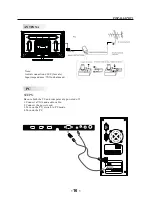
Страница 16: ...l cable not included to the ANT IN jack on the back of your TV DVD combo then connect the other end of the cable into the antenna or cable TV wall outlet To improve picture quality from an antenna in a poor signal area install a signal DPSOL HU If you need to split the antenna signal to connect two TVs install a two way splitter Service Manual Model No 15 ...

Страница 17: ...ale Input impendance 75 unbalanced STEPS PC Be sure both the TV and computer are powered off 1 Connect a VGA and audio cable 2 Connect the power cord 3 Turn on the TV switch to PC mode 4 Turn on the PC HDMI1 HDMI2 USB VGA PC AUDIO HEADPHONE COAXIAL RF 16 ...

Страница 18: ...7 8 9 10 720 400 640 480 640 480 800 600 800 600 1024 768 1024 768 1024 768 1280 1024 1280 1024 70 60 75 60 75 60 70 75 60 75 31 47 31 47 37 50 37 88 46 88 48 36 56 48 60 02 63 98 80 00 RESOLUTION V Freq Hz H Freq KHz 11 1366 768 60 67 50 17 ...

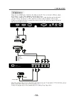
Страница 19: ...to refer to the owner s manual of the device that you are trying to connect HDMI The television s inputs can be connected to the following types of equipment VCR multi disc player DVD camcorder video game or stereo system etc YPbPr can support these video formats 480i 576i 480p 576p 720p 1080i Yellow video White audio L Red audio R or Pr Y W R W R G B R Blue Pb Green Y B G VIDEO EQUIPMENT with YPb...

Страница 20: ... menu When the source device DVD player or Set Top Box supports DVI How To Connect 1 Connect the source device to HDMI port of this TV with a HDMI to DVI cable not supplied with this product 2 A separated audio connection is necessary 3 If the source device has an analog audio output connector connect the source device audio output to DVI Audio In port located on the PC port How To Use If the sour...

Страница 21: ...Cable sample HDMI Cable not supplied with the product HDMI to DVI Cable not supplied with the product Analog Audio Cable Stereo to RCA type not supplied with the product Service Manual Model No 20 ...

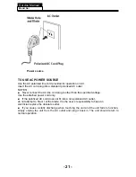
Страница 22: ... Use the attached power cord only Ŷ I WKH SRODUL HG FRUG GRHV QRW W LQWR D QRQ SRODUL HG RXWOHW GR QRW DWWHPSW WR OH RU FXW WKH EODGH W LV WKH XVHUCV UHVSRQVLELOLW WR KDYH DQ electrician replace the obsolete outlet Ŷ I RX FDXVH D VWDWLF GLVFKDUJH ZKHQ WRXFKLQJ WKH XQLW DQG WKH XQLW IDLOV WR IXQFWLRQ simply unplug the unit from the AC outlet and plug it back in The unit should return to normal oper...

Страница 23: ...again to turn the set back to STANDBY Side panel REAR Connections SIDE Connections All the terminals are from left to right HDMI1 HDMI2 USB VGA PC AUDIO HEADPHONE COAXIAL RF Note 1 When HDMI has an input signal coming from a DVI source then the audio input signal must be connected to the PC audio input 30 30 1 3 2 1 2 3 4 5 HDMI1 HDMI2 USB VGA PC AUDIO HEADPHONE COAXIAL RF All the terminals are fr...

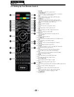
Страница 24: ... eject the disc 17 Press to display the DTV Electronic Program Guide In DVD mode press to go to the previous chapter 18 Press to display the favorite channels list In DVD mode press to go to the next chapter 19 Press to go directly to the HDMI input source 20 Press to go directly to the AV input source 21 Press to display the DTV signal strength 22 Press to go directly to the TV input source 23 Pr...

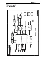
Страница 25: ...N DISTRICT SHENZHEN Custom 2 12 Thursday March 22 2012 1 8VA VGA AUDIO IR LINEIN_L5 R5 OR EUA2113 U705 2 5VA 3 3V_TUNER AL0O AR0O L R 1 8VA DC DC 3 3VA MSD3391DS QFP256 DSP PWM IC AC100V 240V SPIDF OUTPUT COAXIAL TRANSFORMER TDA18273 ONBOARD T102 Q807 RF IN FRONT PANEL SY8008B 12V SPI FLASH 512Mbit SY8008B EFD25 1 32V DC DC VGA RGB USB PORT HDMI 2 IR KEY0 KEY1 IF ATSC TUNER 3 3V_TUNER BLOCK DIAGRA...

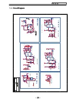
Страница 26: ... 0 1uF EC102 220uF 16V EC102 220uF 16V FB101 10uH 1 5A WSA43 100M R FB101 10uH 1 5A WSA43 100M R SY8008B SOT 23 U105 SY8008B SOT 23 SY8008B SOT 23 U105 SY8008B SOT 23 GND 2 LX 3 VIN 4 OUT FB 5 EN 1 EC111 470uF 16V EC111 470uF 16V R121 100R R121 100R FB103 10uH 1 5A WSA43 100M R FB103 10uH 1 5A WSA43 100M R C116 33P C116 33P R129 820R R129 820R C112 0 1uF C112 0 1uF EC104 220uF 16V EC104 220uF 16V ...

Страница 27: ...2 4 7K C261 10uF C261 10uF CN203 LED IR CN203 LED IR 1 1 2 2 3 3 4 4 5 5 6 6 7 7 8 8 9 9 10 10 R204 33R R204 33R C218 0 1uF C218 0 1uF C242 47nF C242 47nF C238 0 1uF C238 0 1uF C254 2 2uF C254 2 2uF R149 4 7K R149 4 7K R214 33R R214 33R R208 68R R208 68R R230 10K R230 10K C283 10P C283 10P R228 1M R228 1M C202 1uF C202 1uF R275 NC 0R R275 NC 0R R273 NC 33 R273 NC 33 C268 0 1uF C268 0 1uF C270 10uF...

Страница 28: ...23 0 1uF C323 0 1uF C327 0 1uF C327 0 1uF R304 75R R304 75R A B C D E F G H J K L M N P R 1 2 3 7 8 9 Vdd NC Vss DQ14 VssQ UDM VddQ DQ9 VddQ DQ12 VssQ DQ11 Vdd NC Vss DQ6 VssQ LDM VddQ DQ1 VddQ DQ4 VssQ DQ3 VddL Vref Vss CKE WE RFU BA0 BA1 A10 A1 Vss A3 A5 A7 A9 Vdd A12 RFU VssQ UDQS VddQ UDQS VssQ DQ15 VddQ DQ8 VddQ DQ10 VssQ DQ13 VssQ LDQS VddQ LDQS VssQ DQ7 VddQ DQ0 VddQ DQ2 VssQ DQ5 VssDL CK V...

Страница 29: ...V 1 2 R435 1K R435 1K R948 1K R948 1K R718 330R R718 330R L401 0R FB_11_OHM_500MA NC L401 0R FB_11_OHM_500MA NC R409 100R R409 100R R507 5 1R R507 5 1R R422 22K R422 22K C708 1μF 1000P C708 1μF 1000P R502 5 1R R502 5 1R R406 75R R406 75R C819 10P C819 10P R787 NC 10K R787 NC 10K C730 1uF C730 1uF R431 75R R431 75R L707 NC 33uH 2A L707 NC 33uH 2A R516 5 1R R516 5 1R R521 5 1R R521 5 1R C405 33pF C4...

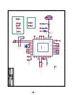
Страница 30: ...721 47nF 25V 10 C721 47nF 25V 10 C723 47nF 25V 10 C723 47nF 25V 10 U701 TDA18273 U701 TDA18273 GNDSYNT 18 VTUN 19 CP 20 XTOUT1 21 XTOUT2 22 CAPREGVCO 17 IFP 25 GNDIF 26 V_IF_AGC 28 VCCIF 27 IRQ 30 V_Sync 29 GNDDIG3 23 IFn 24 VHFSupply 31 VHFL 32 VCCRF 1 RFin 2 NC 3 NC 4 GNDDIG0 5 AS_XTSel 6 GNDDIG1 7 Test1 8 Test2 9 GNDDIG2 10 SCL 11 Test1 13 Xtal 14 SDA 12 Xtalnot 15 VCCSYN 16 40 CapRFAGC RFAGC_S...

Страница 31: ...7uF 400V C1022 680PF C1022 680PF CN2 HEADER 2 CN2 HEADER 2 3 3 4 4 1 1 2 2 R844 200K R844 200K R884 1M R884 1M C1071 0 1uF C1071 0 1uF D804 2A06 D804 2A06 R891 1K R891 1K NP2 NP1 NB1 NB2 NP2 T103 EFD25 NP2 NP1 NB1 NB2 NP2 T103 EFD25 12V 8 GND 10 12V 7 GND 9 11 5V 3 3 2 2 1 1 6 6 5 5 5V 12 4 4 R876 470K R876 470K R829 NC R829 NC R888 1M R888 1M R2297 10K R2297 10K R27 100K R27 100K R865 68K 2W R865...

Страница 32: ...Connection wire Blacklight Service Manual Model No 7 3 Wiring Connection Diagram NO Name 1 2 3 4 5 Connection Wire For Keyboard and Remote Connection Wire For Speaker LVDS Wire 2 3 4 1 31 ...

Страница 33: ... you select some other options the power consumption may change 2 AUDIO menu In this menu you can ajust the sound options here Press to select press OK to adjust In this menu you can adjust the sleep timer time zone etc Press to select press OK to adjust Note 1 Time zone DST Daylight Saving Time and the clock are available in ATSC mode only and the Clock can t be adjusted 4 OPTION menu In this men...

Страница 34: ...ts strongly cautioned Some material may be Inappropriate for children under 13 R NC 17 X Restrict Under 17 requires accompanying parent or adult guardian age varies in some jurisdictions No one 17 and under admitted X is an older rating that is unified with NC 17 but may be encoded in the data of older movies 1 Canada English Switching the English rating control level EXEMPT C C8 G PG 14 18 5 LOCK...

Страница 35: ...8ANS 13 ANS 16ANS 18ANS Rating Description Age E Exempt programming G General All ages and children contains minimal direct violence but may be integrated into the plot in a humorous or unrealistic manner 8ans General but inadvisable for young children May be viewed by a wide public audience but could contain scenes disturbing to children under 8 who cannot distinguish between imaginary and real s...

Страница 36: ...nce of each signal source 4 SSC to adjust the spectrum for passing the EMC test 5 special set 1 2hour off for Aging test 2 WDT watch dog 3 white pattern set pure color output for the panel used at the checking and aging test for panel 4 reset 5 set the recorder 6 set power on screen display 6 QMAP adjust adjust color quality 7 PEQ set sound EQ 8 sw information to check the sofeware information 9 U...

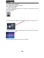
Страница 37: ...w you should choose Yes TV begin to update You should reset TV after update Note When Upgrade on the process please don t Power Off Haier MSD6M182 F W upgrade with USB SOP Step 1 Ready for F W Upgrade 1 1 Prepare a USB memory it from computer s USB port Step 2 F W Upgrade 2 1 AC ON 8 2 How to update software ...

Страница 38: ...hannel 6 Start Menu Display 7 Input Source Change 8 Save to USB 9 Loaking 10 Volume Default Hotel mode switch Panel key lock Hotel mode can adjust the maximum volume Hotel mode locking TV signal source Hotel mode locking program channels Hotel Mode menu is displayed Hotel mode is to display the Source U disk data will be cloned into the machine TV related equipment will be copied to the system U d...

Страница 39: ...Service Manual Model No 9 Trouble shooting 9 1 Simple check 38 ...

Страница 40: ... Q101 Yes Yes No Check if U3 and U4 Pin20 3 3V ǃPin11 5V ǃ Pin19 5V U5 Pin2 0 72V ǃPin3 5V ǃPin4 12V ǃ Pin6 5 7V is normal Change LVDS wire No Replace U3 or U5 U4 Check if Q103 ǃ ǃ D10ǃ D9 ǃ is working Yes Replace Q103ǃ ǃD10ǃ D9 No Service Manual Model No 9 2 Main board failure check 39 Check if there is at C931 30V ...

Страница 41: ...ound input signal No Check the input source Yes No Change L707 L708 Check if there is 12V at Pin15 and Pin28 of U705 Check if there is signal at L203 and L205 No check the signal input circuit of L203 L205 Yes Check if there is input at Pin3ǃPin12 of U705 Yes Change FB1 No Check the speakers Service Manual Model No 40 C739 Check the signal input circuit of C736 C739 and EC807 EC812 L709 L710 ...

Страница 42: ...e voltage pressure of J7 Pin2 is high voltage pressure More than 3V Yes Change U1 No sound No picture Change Mainboard No Yes Check if there is voltage pressure in the pad of the L806 12V ˈ CHANGE Q810 No 41 L2 5V ...

Страница 43: ... power cord to the socket Check if there is voltage pressure in J3 12V ଞ J5 5Vstb Replace Remote Control Board Yes Replace D806 or U2 Still having problems Change Mainboard Check if L101ஂ1 32Vஃଞ L102ஂ1 8VஃଞL103ஂ 3 3VஃଞD101ஂ2 5Vஃis working No Chang U1 Yes Chang U101 OR U102 OR U105 OR D101 No 42 ...

Страница 44: ...is correct Poor sound Change sound system No Update the software and make the reboot or change the Mainboard Still having problems For ease of use recommend that customer format the picture and sound settings in the automatic option 43 ...

Страница 45: ...system Refer to relative instructions in the Manual for color adjust No No Yes Yes Check out of picture and sound system of this channel Change the channel to the right sound system PAL M N PAL D K No color for some channel program black and white Still having problems Updata the software and make the reboot or change the maiboard 44 ...

Страница 46: ...Pin2 in J7 Check J3 voltage of 12 and J8 of 5 No No Yes Yes Replace U1 Replace U1 How to know whether the Power board is broken Still having problems Check if Main board LVDS wire Panel are in good condition No Reconnect the power cord with the outlet or Power board Yes No Check if the break in the power circuit Replace Q806 or Q809 No 45 ...

Страница 47: ... U17 has the right software and work well 5 Verify if the Y1 Crystal has the right frequency Panel not work 1 check if the voltage input and output of boost IC is working normally 2 Verify if the Mainboard output the right On Off signal to power board 3 Verify if the Mainboard output the LVDS singal to panel T con board 4 Verify if the software is the right version of this model 5 Change the LVDS ...

Страница 48: ...check if the power supply if working normally check if the power supply of 5Vstandby is working normally 3 check if the POWER ON OFF voltage is high pressure 4 check if the power supply have 12V 5V output Check if Main board LVDS wire Panel are in good condition 47 ...

Страница 49: ...or cracking Dim or L D TCP Sunken TCP lead cracking ACF bonding short Awful environment and something electric enter into LCD Mis align between TCP and Panel Panel failure TCP failure V Dim Vertal gray line V L D Vertical color line light or dark forever H B D Horizontal bar H Dim Horizontal gary line H L D H o r i z o n t a l line light or dark forever ...

Страница 50: ...er Bubble Bladder in Polarizer Bladder between Polarizer and top glass Polarizer Scratch Polarizer Scratch Tine or rigidity arose F M i n s i d e Polarizer Eyewinker inside Polarizer Eyewinker inside Polarizer Circuit Abnormal Display Abnormal Display 1 Chip lose action 2 IC ahort or jointiog bad 3 Pannel and vsc connect bad Flashing B r i g h t a n d d a r k display alternately 49 ...

Страница 51: ...display Maybe caused by surge current and EDS Black Screen B L normal only Black screen display FIIcker Crosstalk LCD Vcom imbalance Abnormal Color Only color abormal Capacitance improper bring crosstalk inside LCD pannel Abnormal Color Only color abnormal 1 Chip lose action 2 I C s h o r t o r jointion bad 3 Pannel and vsc connect bad ...

Страница 52: ...ss between wire and electrode B L dark B L brightness darker than normal Connect badnessShort between wire and electrode B L wire damaged B L wire damaged Operation abnormal or systemic noise B L wire open Without backlight Operation abnormal or systemic noise B L shut down B L shutdown in sometime Short bitween lamp housing and wire Because consume power too much F M F M inB L white balck Rotundi...

Страница 53: ...ription Phenomena Failure cause Mechanlcal or B L Light leakage Brightness at bottom of LCM brighter than normal B L unit badness Uniformity B L brightness asymmetric Sheet in B L unit is uneven Mount hole Lack screw or screw damage Lack screw Screw damage ...

Страница 54: ...Sincere Forever Haier Group Haier Industrial Park No 1 Haier Road 266101 Qingdao China http www haier com Printed in China ...

Отзывы: