


7
Operation
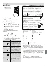
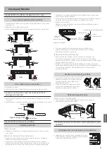
1.After unit starts, select your desired operation mode.
2.Press TIMER button to change TIMER mode. Every
time the button is pressed, display changes as follows:
Remote controller:
BLANK
TIMER ON TIMER OFF
TIMER ON-OFF
Then select your desired TIMER mode (TIMER ON or
TIMER OFF or TIMER ON-OFF). " "or " "will flash.
3.Press /
button to set time.
It can be adjusted within 24 hours.
Hints:
After replacing batteries or a power failure happens, time
setting should be reset.
According to the Time setting sequence of TIMER ON or
TIMER OFF, either Start-Stop or Stop-Start can be achieved.
Timer On/Off On-Off Operation
CE
All the products are in conformity with the following
European provision:
ROHS
The products are fulfilled with the requirements in the
directive
2011/65/EU
of the European p arliament and of
council on the Restriction of the use of Certain Hazardous
Substances in Electrical and Electronic Equipment (EU
RoHS Directive)
WEEE
DISPOSAL REQUIREMENTS:
Your air conditioning product is marked with this
symbol.This means that electrical and electronic
products shall not be mixed with unsorted
household waste. Do not try to dismantle the
system yourself : the dismantling of the air
EUROPEAN REGULATIONS
CONFORMITY FOR THE MODELS
1
1+2=
kg
R32
2
kg
2=
1=
B
C
D
F
E
kg
A
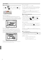
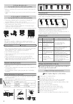
This product contains fluorinated greenhouse gases covered by
the Kyoto Protocol. Do not vent into the atmosphere.
Refrigerant type:R32
GWP* value:675
GWP=global warming potential
Please fill in with indelible ink,
and
on the refrigerant charge label supplied with the product.
The filled out label must be adhered in the proximity of the product
charging port (e.g. onto the inside of the stop value cover).
A contains fluorinated greenhouse gases covered by the Kyoto
Protocol
B factory refrigerant charge of the product: see unit name plate
C additional refrigerant amount charged in the field
D total refrigerant charge
E outdoor unit
F refrigerant cylinder and manifold for charging
IMPORTANT INFORMATION REGA-
RDING THE REFRIGERANT USED
In accordance with the directive
2012/19/EU
of the European
parliament, herewith we inform the consumer about the dis-
posal requirements of the electrical and electronic products.
conditioning system,treatment of the refrigerant, of oil and of
other part must be done by a qualified installer in
accordance
with relevant local and national legislation. Air conditioners
must be treated at a specialized treatment facility for reuse,
recycling and recovery. By ensuring this product is disposed
of correctly, you will help to prevent potential negative cons-
equences for the environment and humen health. Please
contact the installer or local authority for more information.
Battery must be removed from the remote controller and dis-
posed of separately in accordance with relevant local and
nationl legislation.
Contains fluorinated greenhouse gases
covered by the Kyoto Protocol
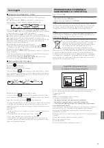
Healthy airflow Operation
1.Press to starting
Setting the comfort work conditions.
2.The setting of healthy airflow function
Note:
1.After setting the healthy airflow function, the position
grill is fixed.
4.In cooling and dry, using the air conditioner for a long
time under the high air humidity, condensate water may
occur at the grille .
3.The cancel of the healthy airflow function
Notice: Do not direct the flap by hand. Otherwise, the
grille will run incorrectly. If the grille is not run correctly, stop
for a minute and then start, adjusting by remote
controller.
2.In heating, it is better to select the
3.In cooling, it is better to select the
mode.
mode.
TIMER OFF-ON
0.5h
0.5h
0.5h
0.5h
Press the button for each time, setting time in the first
12 hours increased by 0.5 hour every time, after 12
hours,increased by 1 hour every time.
Press the button for each time, settiing time in the first
12 hours decreased by 0.5 hour every time, after 12
hours,decreased by 1 hour every time.
After adjust the time,press button and confirm the
time ON or OFF button will not flash any more.
4.Confirm timer setting
5.Cancel timer setting
Press the timer button by times until the time display
eliminated.
Press button to enter additional options,Press this
button continuously, the louvers location will cycle between
in the following three locations, to choose the swing location
what you needed,and then press button to confirm.
Press button to enter additional options,Press this
button continuously, the louvers location will cycle between
in the following three locations again,and then press
button to cancel.
Healthy
airflow
upwarder
Healthy
airflow
downwarder
Present
position
Voltage:230V
Climate:T1
2014/53/EU(RED) 2014/517/EU(F-GAS)
2009/125/EC(ENERGY)
2010/30/EU(ENERGY)
2006/1907/EC(REACH)
WIFI
-Wireless maximum transmit power (20dBm)
-Wireless operating frequency range (2400~2483.5MHz)
Содержание IKI-09
Страница 14: ...1 2m2 8 H07RN F 3mm R32 A R32...
Страница 15: ...24 16 17 23 20 25...
Страница 20: ...20 17 22 26 17 19 26 FC R32 15 10 10 2m...
Страница 23: ...23 40 C 1 2 3 4 FRONT stopper 5 1 2 4 5 l 6 l l 3 OFF M...
Страница 24: ...24 1 2 3 OFF...
Страница 26: ...211 300 3300...
Страница 27: ......
Страница 28: ......


