background image

Содержание IKI-09

Страница 1: ...ENGLISH USER S MANUAL AIR CONDITIONING SYSTEMS WALL MOUNTED UNIT MODELS IKI 09 IKO 09 IKI 12 IKO 12 IKI 18 IKO 18 IKI 24 IKO 24...

Страница 2: ...ntacts should not be no less than 3mm Such means for disconnection must be incorporated in the Make sure installation is done according to local wiring regulation by professional persons A leakage exp...

Страница 3: ...12 4 5 11 8 Contents PARTS AND FUNCTIONS OPERATION INDOOR UNIT INSTALLAION MAINTENANCE CAUTIONS TROUBLE SHOOTING 13...

Страница 4: ...lay TIMER ON display 7 TEMP display 16 LOCK button Used to lock buttons and LCD display 25 RESET button When the remote controller appears abnormal use a sharp pointed article to press this button to...

Страница 5: ...ilable in FAN mode And temp setting is disabled In FAN mode sleep operation is not available Emergency Operation Use this operation only when the remote controller is defective or lost and with functi...

Страница 6: ...ion will be cancelled Press button to enter additional options when cycle display to will flash and then press enter to power function When cancel the function please enter additional options again an...

Страница 7: ...a qualified installer in accordance with relevant local and national legislation Air conditioners must be treated at a specialized treatment facility for reuse recycling and recovery By ensuring this...

Страница 8: ...not disturbed Place possible to drain easily where piping can be conne cted with the outdoor unit Place where cold air can be spread in a room entirely Place nearby a power receptacle with enough spac...

Страница 9: ...rst fixed for the Making a Hole on the Wall and Fitting the Piping Hole Cover Drawing of pipe Installation of the Indoor Unit Rear piping Draw pipes and the drain hose then fasten them with the adhes...

Страница 10: ...or due to wiring error Faulty PCB Faulty EEPROM data Faulty EEPROM Faulty PCB Faulty connector connection Faulty therm istor Faulty PCB Room temperature sensor failure The power source must be exclusi...

Страница 11: ...indoor unit using vacuum cleaner or flaping them lightly otherwise its performance will be affected the cool and dry conditions For Smart Use of The Air Conditioner Replacement of Air Purifying Filter...

Страница 12: ...BITION PROHIBITION PROHIBITION PROHIBITION Do not start or stop the operation by disconnecting Do not channel the air flow directly at people especially at infants or the aged Do not try to repair or...

Страница 13: ...y cord is damaged it must be replaced manufacturer qualified person 4 The wiring method should be in line with the local wiring 5 After installation the power plug should be easily reached 6 The waste...

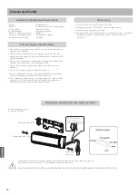
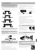
Страница 14: ...1 2m2 8 H07RN F 3mm R32 A R32...

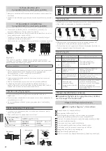
Страница 15: ...24 16 17 23 20 25...

Страница 16: ...18 POWER ON OFF 19 DRY 20 TEMP 21 SWING 22 HOUR 23 EXTRA FUNCTION 1 2 24 CANCEL CONFIRM CANCEL CONFIRM 25 RESET RESET 1 2 3 SWING 4 FAN SPEED 5 LOCK 6 TIMER OFF TIMER ON 7 TEMP 1 2 2 R 03 3 4 7m 1 2 3...

Страница 17: ...P 1 C 4 FAN To AUTO 2 4 3 2 3 4 COOL DRY 1 1 COOL DRY AUTO 2 3 4 5 AUTO AUTO AUTO COOL DRY DRY 2 C LOW FAN HEAT HEAT AUTO FAN FAN COOL HEAT FAN AUTO SLEEP FAN 16 C 5 Hi TIMER DRY TIMER 23 C 26 C AUTO...

Страница 18: ...2 HEAT 1 SLEEP 2 C 1 2 C 3 1 C 3 4 FAN SLEEP 5 TIMER TIMER POWER QUIET HEALTH 1 POWER 2 QUIET QUIET QUIET QUIET QUIET POWER HEAT COOL QUIET 3 AUTO HEALTH HEALTH HEALTH 1 1 2 3 3 O C 2O C 1 O C SLEEP...

Страница 19: ...FF TIMER ON OFF OFF 3 12 0 5 12 1 12 0 5 12 1 24 4 OFF 5 TIMER TIMER TIMER OFF Start Stop Stop Start 230V CE 2014 35 2014 30 ROHS 2011 65 RoHS WEEE 2012 19 R32 GWP 675 GWP 1 2 1 2 A C D F 1 2 3 1 2 3...

Страница 20: ...20 17 22 26 17 19 26 FC R32 15 10 10 2m...

Страница 21: ...2 60 mm 3 l 1 2 3 4 60mm G A 150mm C 120mm C 113mm B 60mm A 70mm B 60mm B 60mm B 60mm 30mm 45mm 45mm 30mm 35mm 35mm B 60mm B 60mm A 120mm C 80mm A 130mm C 110mm 35mm 35mm B 60mm B 60mm IKI 09 IKI 12...

Страница 22: ...22 R410A A 0 0 5 mm 1 0 1 5 mm 1 5 2 0mm 1 2 3 4 5 1 2 4G1 00mm2 1 H07RN F 2 T 3 15A 250VAC 3 4 5 3mm 5 6 7 A 8 A 1 PCB 2 4 EEPROM EEPROM EEPROM PCB 7 14 PCB 9 E...

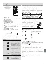
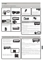
Страница 23: ...23 40 C 1 2 3 4 FRONT stopper 5 1 2 4 5 l 6 l l 3 OFF M...

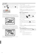
Страница 24: ...24 1 2 3 OFF...

Страница 25: ...RY dry DRY 2o C 15 T 1 D B W B 32 C 23 C D B W B 21 C 15 D B W 46 26 C D B 15 C D B 27 C D B 15 C D B W B 24 C 18 C D B W B 7 C 8 C INVERTER D B W B 24 C 18 C D B 15 C 2 3 3 15 250V T 25A 250V 4 5 6 7...

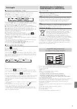
Страница 26: ...211 300 3300...

Страница 27: ......

Страница 28: ......

Отзывы: