background image


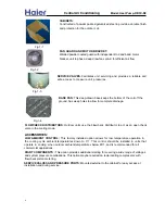
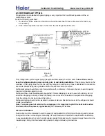
Fig.4-5 

SERVICE VALVES 

The stem or core is removable with a flexible seal at its base held closed with a spring. Schrader valves 
allow a technician to connect gages to the system with a minimum loss of charge. Use a cap with an 


5.ELECTRICAL CONTROL DEVICES   

PROTECTION DEVICES 

Protection for the unit begins with the installation of appropriate fuses or circuit breakers by the installing 

OVERLOADS AND LIMITS 

include the automatic reset internal overload in the fan motor and the compressor automatic reset 
internal overload. Such controls are not serviceable but their operation may influence service 
troubleshooting .For example, the compressor internal overload may stay open for several hours .A 

refrigerant pressure exceeds a pre-determined limit of 440 to 460 p.s.i.g. 

When pressure becomes


THERMOSTATS  

In the cooling mode, the thermostat calls for cooling by energizing the compressor contactor and the
indoor blower control. The indoor blower can operate continuously by setting the thermostat subbase fan
switch to the “ON” position. 

subbase selection information found in the wiring diagram booklet. 

various manual changeover, auto changeover and set-back thermostats or see the thermostat and  

accessible by the consumer. Contact your local distributor for information on part numbers of 

or 

“Schrader valve” and the refrigerant line valve. The Schrader valve is like a valve in an automobile tire. 

inner seal to prevent leakage and keep dirt and moisture from entering the system. 

systems, these valves also hold the charge in the outdoor section from factory. 

Refrigerant control valves allow the outdoor unit to be isolated into from the balance of the system. In split 

Thermostats are the most obvious control in the air conditioning system because these controls are  

contractor. Breaker or fuse size is governed by the National Electrical Code and local code. AMP draw 

Overloads protect against over-current or over-temperature conditions. Those located in the outdoor unit 

requirements for each unit are found in the Specifications. 

technician may incorrectly diagnose this as an open compressor winding. 

The high pressure cut-out is a pressure activated switch. It opens an electrical circuit when the 

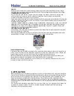
HIGH PRESSURE CUT OUT SWITCH (optional) (Fig. 5-1) 

normal, the 

switch 

restores automatically


Fig.  5 -1 

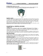
REFRIGERANT CIRCUIT (Fig. 4-5) 

All 13SEER units outdoor coils are multi-circuit. Refrigerent gas or liquid is uniformly distributed to from

There are two types of service valve used on these air conditioning units. They are the service port valve  

4 to 10 circuits to improve heat transfer and reduce capacity losses due to pressure drops. 

10


                         Central Air Conditi

oning   


Model: Heat Pump, 

HR13-D2


Содержание HR18D2VAR

Страница 1: ...ign Benchmark hermetic compressor design Powder coated full metal jacket Efficient performance and economical operation Durable construction Quick easy installation and service HR18D2VAR HR30D2VAR HR36D2VAR HR24D2VAR Compact design Manual code SYJS 014 07REV 0 Edition 2007 04 02 Heat pump Value Series HR13 D2 ...

Страница 2: ...ssary to work with circuits with live electrical components Only individuals with proper training that can follow all electrical safety precautions should perform this work Failure to follow all safety precautions could result in property damage serious injury or death 3 SAFETY PRECAUTION 8 5 ELECTRICAL CONTROL DEVICES 10 7 REFRIGERANT DIAGRAM 13 4 SYSTEM COMPONENTS AND FUNCTIONS 8 6 APPLICATION 1...

Страница 3: ...PTION OF PRODUCTS FEATURES This manual discusses split central air conditioning and indoor coils Split central air condition system refers to the physical location of major air conditioning components The split system air conditioning are manufactured to standards of quality and performance They are 13 SEER Seasonal Engery Efficiency Ratio which meet or exceed the standards imposed by efficiency l...

Страница 4: ...in cooling when outdoor ambient temperatures below 65 and is recommended for all commercial applications and system pressure combinations This option maybe required on reciprocating compressors with START COMPONENTS This option provides additional starting for covering a wide range of voltages SERVICE VALVES AND PRESSURE PORTS Mounted external to the cabinet for easy access at installation and dur...

Страница 5: ...Reciprocating Reciprocating Reciprocating H21J14BABCA H21J19BABCA H21J24BABCA H21J30BABCA 5 4 8 0 10 1 11 8 36 0 53 5 61 0 78 0 Yes Yes Yes Yes Yes Yes Yes Yes 0 86 0 86 1 4 1 6 1 8 1 8 1 4 1 3 1000 1000 1075 1120 175 0 175 0 210 0 325 0 18 18 18 18 3 3 3 4 Zinc Coated Steel Zinc Coated Steel Zinc Coated Steel Aluminium Performance Electrical Compressor with Matching Indoor Unit Fan Motor No of Bl...

Страница 6: ... Optional Optional Optional Optional Yes Yes Yes Yes Haier Enhanced Coil Haier Enhanced Coil Haier Enhanced Coil Haier Enhanced Coil Yes Yes Yes Yes Yes Yes Yes Yes Yes Yes Yes Yes Yes Yes Yes Yes No No No No Yes Yes Yes Yes Yes Yes Yes Yes Yes Yes Yes Yes Optional Optional Optional Optional No No No No Optional Optional Optional Optional Yes Yes Yes Yes No No No No Yes Yes Yes Yes Yes Yes Yes Yes...

Страница 7: ... Orifice 078 062 R 22 104 24 R 22 107 77 R 22 141 34 R 22 148 41 10 sides 18 service 10 sides 18 service 10 sides 18 service 10 sides 18 service 167 0 172 0 189 0 207 0 183 0 187 0 205 0 222 0 ARI ARI ARI ARI UL cUL UL cUL UL cUL UL cUL Basiloid Basiloid Basiloid Basiloid Height 28 1 2 28 1 2 28 1 2 32 Width 26 7 8 26 7 8 26 7 8 26 7 8 Depth 26 7 8 26 7 8 26 7 8 26 7 8 11 92 11 92 11 92 13 38 5 5 ...

Страница 8: ...IFE AND OR INJURY RESULTING FROM THE USE OF SUCH UNAUTHORIZED COMPONENTS OR PROPERTY THE MANUFACTURER DISCLAIMS ANY RESPONSIBILITY FOR SUCH LOSS ACCESSORIES performing system maintenance Current single phase units use two types of compressors The design of the two compressors types is to move refrigerant When paired motor with low pressure through proper refrigrant control Returning refrigerant co...

Страница 9: ...This fan pulls outdoor air through the outdoor coil To access the condenser fan or motor carefully remove the unit top a service loop is provided on the motor wiring for easier access METERING DEVICES Fig 4 4 One type of refrigerant metering device is the flow check piston It has two functions First it acts as a When refrigerant enters the device from the square end the piston seats and forces all...

Страница 10: ...al distributor for information on part numbers of or Schrader valve and the refrigerant line valve The Schrader valve is like a valve in an automobile tire inner seal to prevent leakage and keep dirt and moisture from entering the system systems these valves also hold the charge in the outdoor section from factory Refrigerant control valves allow the outdoor unit to be isolated into from the balan...

Страница 11: ... APPLICATION of America ACCA J Manual method of load calculation is one recognized procedure for determining the Fig 5 2 Generallyrelaysusedinairconditioninguse24VACcoils Contactvoltagemaybeeitherloworlinevoltage Relays provide a method for control switching Relays may switch either low 24VAC or line voltage Single polecontactorsbreakonlyonesideofthepowerfeedtothecompressorandoutdoorfan Theothersi...

Страница 12: ...d off quickly and does not properly remove humidify producing uncomfortable The indoor and outdoor equipment combination should be matched by the manufacturer There are several factors that installers must consider and based on engineering data conditioning requirements the system must be properly installed Proper installation with cerefully distributed air through adequate duct work will provided...

Страница 13: ...tically through bad planning or workmanship In cooling a hot attic can cause a temperature gain ton system is only 30 CFM Two or three unsealed joints can cause a leak of this size Sealing the return and supply ducts result in full system capacity and lower operating costs the duct system is totally in the responsibility of the contractor These are numerous thchnical associations Low indoor air fl...

Страница 14: ...Figure 7 Heat Pump Refrigerant Circuit 14 Central Air Conditioning Model Heat Pump HR13 D2 ...

Страница 15: ...cian The manufacturer s warranty does not cover any damage failure caused by the air conditioning system components accessories or devices for loss or injury due to the use of such unauthorized Attach the service panel to the outdoor unit after to prevent If the service panel is not attached securely it could result in a fire or an electric shock due to dust water etc This product has been inspect...

Страница 16: ...e unit Location where roof runoff does not pour directly on the unit Avdid locating the unit in an area where excessive snow can accomulate or drifting occur parts and can vibrate so sound transmission is also a consideration in rooftop applications from the service access area A typical application will find the unit located about 10 from wall with discharges upward from the top of the unit Refri...

Страница 17: ... 50 feet or line size correction may be necessary 2 If the vertical separation exceeds 10 feet use the next larger liquid line size WHEN INDOOR UNIT IS 4 FEET OR MORE BELOW OUTDOOR UNIT A SUCTION LINE OIL TRAP IS REQUIRED PROVDE ADDITIONAL TRAPS FOR EVERY 20 FEET OF LIFT keep the refrigerant tubing clean and dry prior to and during installation If there is any doubt on the loss and increased opera...

Страница 18: ...B such as kitchens boiler rooms hot attics or on the roof then they should be insulated as well Liquid lines do not necessarily need insulation however if they are run in high ambient spaces Make sure to use proper size copper tubing for the liquid line to prevent liquid refrigerant flashing Keep the vapor line and liquid line seperated To prevent an undesirable heat transfer and capacity loss 2 0...

Страница 19: ... at least 10 minutes to allow pressure to stabilize between thermometer and line Wrap thermometer with insulating material to assure accurate reading 5 Refer to Table 8 2 for proper system superheat Add charge to lower superheat Remove charge to raise superheat Carefully remove guage 8 7 Charging the System 6 Braze the joints of interconnecting piping purge piping with dry nitrogen through the shu...

Страница 20: ...cal work should be performed by knowledgeable personals according to national codes and in accordance with this installation manual Ground the unit According to the national electric code Electrical installation consists of power supply wiring to the condensing unit and control wiring between thermostat indoor unit and the condensing unit All wiring must be in accordance with National Electrical C...

Страница 21: ... Conductors Below The installer must be familiar with the location of the over current protection properly size for this this application and the proper procedure for disconnecting power service to the unit transformer as shown on the wiring diagram The outdoor unit control wiring requires a 24 Volt minimum 25 VA service from the indoor The location of the disconnect device must be in accordance w...

Страница 22: ...set point This sends a 24 voltage signal through the Y terminal to the outdoor unit PCB after 3 minutes the compressor contact in the outdoor unit are closed The compressor and outdoor fan start At the same time a 24 Voltage signal flows through the G Terminal to the air handler PCB and 8 Check unit for tubing and sheet metal rattles 2 Turn temperature setting above the room temperature 5 Check to...

Страница 23: ...coil clippings or other material to obstruct the coil Do not allow anything to block the coil Keep fences A Before cleaning coil TURN OFF ELECTRICAL POWER to the outdoor unit SERVICE OR MAINTENANCE A Vacuum clean or B Wash with detergent and water air dry thoroughly and re install 10 SERVICE AND TROUBLESHOOTING WARNING THE ABILITY TO PROPERLY PERFORM SERVICE ON THIS EQUIPMENT REQUIRES EXPERIENCE M...

Страница 24: ...ompleting this checklist the conditioning system call for your records The following test equipment is recommended to properly service air conditioning equipment RECYCLINE DEVICE WHEN DOING REFRIGERANT SERVICE 1 A good quality volt ohm meter 3 A Magnetic Gauge capable of reading to 3 W C 5 A clamp on ammeter 7 A micron meter not shown 9 Refrigerant recovery recycling equipment 2 A two channel temp...

Страница 25: ...loping No evidence of refrigerant leaks Unit charged according to manufacturer s instructions No kinks or restrictions Adequate clearances for air flow and service No evidence of refrigerant leaks Proper supply and return air duct size and design Correct filter s Correct indoor coil and accessories External static pressure_____ inches W C Horizontal drain pan installed in horizontal applications W...

Страница 26: ...ity 6 7 MECHANICAL Some compressors require the assistance of a hard start kit to start it is urgest to consult the indoor motors usually are multi speed All fan motors require a capacitor for the best torque and efficiency If the motor is replaced replace the capacitor at the same time information compressor manufactores recommendations for start kits follow the manufactores installation MOTORS E...

Страница 27: ... component being checked 3 Measure the resistance of the holding coil with an ohmmeter 4 Measure the resistance across the normally closed NC relay contacts A The resistance should be zero 0 ohms 5 Measure the resistance across the normally open NO relay contacts A The resistance should be Infinite MECHANICAL CHECKS AIR FLOW characteristics Relay contacts are switches and can become pitted or corr...

Страница 28: ...emperature TS AMPS 3 414 entering and leaving the heater and calculating the CFM Compressor manufacturers state that maul of the compressors returned as defective have been failed or if another control has either failed or stopped the compressor from operating after detecting a Prior to replacing a suspected failed compresso a thorough check must be made of all existing electrical electrical compo...

Страница 29: ...n Ohms B Run to Common Ohms CONSLUSION COMPRESSOR COULD HAVE AN OPEN INTERNAL OVERLOAD ALLOW THE COMPRESSOR MOTOR TO COOL AND THE INTERNAL OVERLOAD TO RESET THEN RETEST C Run to Common 1 0 ohms Start to Run Ohms COMPRESSOR MECHANICAL CHECKS system Bearing and valve failure is almost always caused by liquid refrigerant COMPRESSORS ARE or breaking them Liquid refrigerant also damages bearings by dil...

Страница 30: ...ressor by REMOVING EACH WIRE FROM THE COMPRESSOR TERMINALS NOT THE COMPRESSOR TERMINALS THESE WIRE ENDS WILL BE AND GNERGISED HOT DURING THE REMINDER OF THE TEST Run the condensing fan until the leaving air temperature equals to the entering air temperature This Close the disconnect switch to the system and run the condensing fan Measure the condensing coil Compare the observed refrigerant pressur...

Страница 31: ...ping damage The line connections must come electrical characteristics as the original sealed from the factory Verify that the replacement compressor is the same model number and F If any burn detected replace the liquid line filter drier with an oversized core filter drier if the burn was severe and a suction line filter drier E Remove the caps from the compressor stubs clean the lines and stubs a...

Страница 32: ...are tight C Verify that all fuses or circuit breakers are of the proper type and operational G Verify all ducts and air moving device are sized and operate properly Verify all the system are in correct position D Verify the air conditioning operates properly in cooling Verify the thermostat and subbase are correct and operate properly H Verify the refrigerant piping is sized correctly and not pinc...

Страница 33: ...ton size too small Change to correct size piston High head Low vapor pressures Incorrect capillary tubes Change coil assembly Blocked outdoor coil Clear away leaves and other debris Refrigerant overcharge Correct system charge Condenser fan not running Repair or replace High head High or normal vapor pressures Air non condensibles or moisture in system Recover refrigerant evacuate recharge add fil...

Страница 34: ...tor function When LED is used as failure indication refer to the failure code Electric control board and function for central air conditioner Heat pump control board Note 1 2 second flash sycle indicates problem indication Failure indication LED will flash for alarm Flash frequency 0 5 second on and 0 5 second off with a 2 seconds interval between flashes 34 Central Air Conditioning Model Heat Pum...

Страница 35: ...ionship between the dip switch setting and the compressor winding circles accross CT please refers to the wiring diagram with the unit 3 1 Outdoor coil temp sensor R25 5KΩ B25 50 3450K with copper terminal T Rnom KΩ T Rnom KΩ T Rnom KΩ T Rnom KΩ T Rnom KΩ 4 47 12 28 4 19 39 60 8 7 661 93 2 3 368 125 6 1 667 2 2 45 17 30 2 18 39 62 6 7 295 95 3 23 127 4 1 608 0 4 43 24 32 17 45 64 4 6 949 96 8 3 09...

Страница 36: ... pre set See the figure from left to right they are 1 2 3 4 5 6 4 2 CN2 24VAC control signal 0VAC neutral line output to control AC contactor winding 4 3 CN3 24VAC control signal 0VAC neutral line output to control 4 way valve winding 4 4 CN4 CN5 fan motor control port to control the neutral line of outdoor motor 4 5 CN6 outdoor coil temp sensor connector the coil temp sensor connected disconnecte...

Страница 37: ...e the units start the system will alarm immidately If the pressure switch hasn t acts before the units start the system will alarm only when the switch acts 3 times within 30 minutes the failure can not be resumable Please reset the power to clear the alarm 4 9 CT current value detected by current mutual inductor after compressor is running the running current will be detected if it is over curren...

Страница 38: ...15min yes Check and reconnect no record Tp0 after compressor on for 8 min heat pump mode Tp Tp0 23 for 3 min or Tp 10 4 for 3 min Tp Tp0 26 6 for 3 min or Tp 10 4 for 3 min 5 1 Defrosting procedure SW1 1 OFF SW1 2 OFF heat pump mode record Tp0 after compressor on for 8 min no Check and reconnect yes Is Tp pipe temp 35 6 for 10 sec 30min the compressor runtime 15min yes yes yes Tp Tp0 10 4 for 3 mi...

Страница 39: ...nsor yes short the XT port see whether defrost replace PCB no yes yes no does the dip switch at proper position refer to wire diagram 5 3 Troubleshooting does the unit work properly does there show any default change the dip switch to right position code range 13K for 35 6 and 37k for set pipe temp to about 32 and use a ring to ally between this 4 norm 39 Central Air Conditioning Model Heat Pump H...

Страница 40: ...WIRING TO CONFORM TO I E C N E C C E C C L C AND LOCAL CODES AS APPLICABLE REPLACEMENT WIRE MUST BE THE SAME GAGE AND INSULATION TYPE AS ORIGINAL WIRE CMPR UNIT OUTDOOR 6 C BK CCH L1 GND L2 208 230V RVS 60Hz 1PH 1 OFF OFF Dip 1 Dip 2 R WH BK M HR36E1VAR HR30E1VAR HR60E1VAR HR36D2VAR HR30D2VAR OFF ON ON ON HR60D2VAR OFF OFF OFF OFF 1 Confirm defrost control board DFC dip switch settings and CT appl...

Страница 41: ...Sincere Forever Haier Group Haier Industrial Park No 1 Haier Road 266101 Qingdao China http www haier com Central Air Conditioning Model Heat Pump HR13 D2 ...

Отзывы: