Pin number
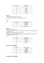
Signal number
1 SW
2 GND
3 +5VSB
4 GND
5 GND
6 +12V
7 +12V
Notes:
CNA1-Pin1:System power on / standby
System board will use this pin to control system power.
CN1
Pin number
Signal number
1 Dimming
2 ON/OFF
3 GND
4 SELECT(NC)
Notes:
CN1-Pin2: Backlight on/off
The system can turn on or turn off the backlight of TFT LCD Panel through the power
supply unit path.
CN1-Pin1: Control the luminance of backlight.
The system can generate the PWN signal to control the strength of TFT LCD Panel’s
backlight through this connector.
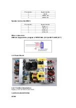
CNA2
Pin number
Signal number
1 +24V/16.5V
2 +24V/16.5V
3 GND
4 GND
Remote connector(CNE1)
Pin number
Signal number
1 +5VSB
2 IR_IN
3 LED_RED
4 LED_GRE
5 GND
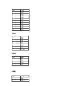
Keypad connector(CNE2)
Содержание HLC32R1 - 32" LCD TV
Страница 10: ...CON3 CON4 CON5 ...
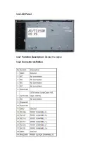
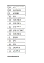
Страница 11: ...3 4 LCD Panel 3 4 1 Function Description Display the signal 3 4 2 Connector definition ...
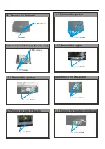
Страница 12: ...4 Disassemble and assemble ...
Страница 14: ...4 9 Remove the terminal bracket Screw Screw 4 10 Remove the connection to the panel ...
Страница 26: ...7 Electrical parts 7 1 Block diagram 7 2 Circuit Diagram MTK5380L MT8292 TPA3101 ...
Страница 42: ......
Страница 48: ...42 Clean Storage The function could make the model turn back to the factory default setting ...


