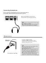
background image

5

5

4

4

3

3

2

2

1

1

D

D

C

C

B

B

A

A

NEARLY YPBPR CONNECTOR

NEARLY MT5380

NEARLY MT5380

NEARLY YPBPR CONNECTOR

NEARLY IC

NEARLY IC

COAXIAL

DVD

输入

YPBPR

NEARLY YPBPR CONNECTOR

L/R_USB/DVBT/DVD

输入

YPBPR1/DVD_SEL=1::DVD

YPBPR1/DVD_SEL=0::YPBPR1

F O R : D V D _ I N

3

Top View

4

2

5

SPDIF

Out(Vertical)

SPDIF OUT(Vertical)

1

+5V

AVDD12_RGBADC

AVDD12_RGBFE

HSYNC

VSYNC

BP
BN

RN

SOY0

SOG

GP
GN

RP

PR0P

Y0P
Y0N
PB0P
PBR0N

AVDD12_RGBFE

AVSS12_RGBFE

AVDD12_RGBADC

AVSS12_RGBADC

DVDD12_VGA

DVDD12_VGA

BP
BN

RN

SOG
GP
GN
RP

HSYNC
VSYNC

AIN2_R

AIN2_L

Y0P

Y0N

SOY0

PB0P

PBR0N

PR0P

PB0_IN

ASPDIF

AV12

GPIO_5

PR0_IN

SOY1

PBR1N

YPBPR1_PR1_IN

Y1N

PR1P

Y1P

Y1_IN

PB1P

PB1_IN

PR1_IN

PBR1N
PR1P

Y1P
Y1N

SOY1

PB1P

AIN3_L
AIN3_R

AIN3_L

AIN3_R

YPBPR1L_IN

YPBPR1R_IN

YPBPR1R_IN

YPBPR1L_IN

YPBPR0L_IN

YPBPR0R_IN

AIN2_R

AIN2_L

YPBPR0L_IN

YPBPR0R_IN

YPBPR0R_IN

PB0_IN

PR0_IN

YPBPR0L_IN

PB1#

PR1#

Y0_IN

Y0_IN

DVD_Y1

DVD_L_IN

DVD_R_IN

Y1#

YPBPR1_PB1_IN

DVD_Y1_IN

YPBPR1_Y1_IN

DVD_PR1_IN

Y1#

YPBPR1_PB1_IN#

YPBPR1_PR1_IN

YPBPR1_PR1_IN#

PR1#

YPBPR1_PB1_IN#

DVD_PR1_IN#

DVD_Y1_IN#

DVD_Y1_IN#

DVD_PR1_IN#

YPBPR1/DVD_SEL

DVD_Y1_IN

YPBPR1_Y1_IN

PB1#

DVD_PB1_IN

DVD_PB1_IN#

DVD_PB1_IN#

YPBPR1_PR1_IN#

YPBPR1_Y1_IN#

YPBPR1_Y1_IN#

+12V

AV33

YPBPR0_DET

DVD_DET#

MGPIO8

8292_MGPIO8

MGPIO2

YPBPR1_DET#

8292_MGPIO2

YPBPR1_DET

MGPIO1

8292_MGPIO1

YPBPR0_DET#

YPBPR0_DET

Y1_IN

PR1_IN

YPBPR1L_IN

YPBPR1R_IN

PB1_IN

DVD_DET

YPBPR1_DET

YPBPR1_PB1_IN

DVD_L_IN

DVD_L_IN

IR_IN

8292_MGPIO7

+5VSB

MGPIO7

8292_MGPIO7

DVD_POWER#

DVD_POWER

DVD_POWER

IR_IN

ASPDIF

SPDIF

DVD_PB1_IN

SPDIF

DVD_R_IN

GND

DVD_R_IN

Y_GND

DVD_Y1

Y_GND

Y_GND

AVSS12_RGBFE

DVD_PR1

AVSS12_RGBADC

GND

DVD_PR1

DVD_DET

PB_GND

PB_GND

PB_GND

DVD_PR1_IN

DVD_IR

DVD_PB1

DVD_PB1

DVD_DET

DVD_IR

+3V3SB

GND

1,2,3,4,5,6,7,8,9,11,12,13,14,15

+5V

1,2,3,4,5,8,9,15

HSYNC

11

VSYNC

11

BP

11

BN

11

SOG

11

GP

11

GN

11

RP

11

RN

11

AIN2_L

13

AIN2_R

13

ASPDIF

13

AV12

3,5,8

GPIO_5

4,8

AIN3_R

13

AIN3_L

13

DVD/DVBT/USB_L_IN

14

DVD/DVBT/USB_R_IN

14

+12V

1,3,9,15

AV33

2,3,5,8,9,13

8292_MGPIO8 14

8292_MGPIO2 14

8292_MGPIO1 14

IR_IN

1

8292_MGPIO7

14

+5VSB

1,2,11,15

8292_MGPIO7 14

+3V3SB

1,2,4,7,8,9,13

AV12

AV12

AV12

AV33

AV33

AV33

AV33

AV33

AV33

AV33

AV33

+5V

AV33

+3V3SB

TP7

C694
15pF->18pF

C0402/SMD

TP96

R1850
10K

R0603/SMD

CE644

10uF/10V

C0805/SMD

R1200

68

R0603/SMD

R1834

NC/0

R0603/SMD

CE647

10uF/10V

C0805/SMD

C635

4.7uF/6.3V

C0805/SMD

TP101

CE645

10uF/10V

C0805/SMD

R1641

68

R0603/SMD

R41
4.7K

R0603/SMD

R1847
10K

R0603/SMD

C115
1uF

C0402/SMD

C351

10nF

C0402/SMD

C349

4.7nF

C0603/SMD

D105
ESD_0402_10pF

C0402/SMD

1

2

TP8

D193

ESD_0402_10pF

C0402/SMD

1

2

C592

4.7nF

C0603/SMD

U53

PI5V330

TSSOP16/SMD/HAIER

6

2
3

1

4
5

7
8

14

15

13

11

12

16

10
9

I1B

I0A
I1A

S

YA
I0B

YB
GND

I0D

E#

I1D

I0C

YD

VCC

I1C

YC

R1635

100

R0603/SMD

CON43

SPDIF_V

GQ-13_Haier_B

3

2

1

4

5

GND

VCC

IN

4

5

R1639

100

R0603/SMD

R38
1K

R0603/SMD

R1184

68

R0603/SMD

C363

10nF

C0402/SMD

CE648

10uF/10V

C0805/SMD

R1836
10K

R0603/SMD

C353
15pF

C0402/SMD

R1640

75

R0603/SMD

R1636

68

R0603/SMD

R1842
10K

R0603/SMD

C636

4.7uF/6.3V

C0805/SMD

R1878

1K

R0603/SMD

D157
ESD_0402_10pF

C0402/SMD

1

2

R1831
75

R0603/SMD

R153

20K->33K

R0603/SMD

Q5

MMBT3906

SOT23

1

2

3

R1848
10K

R0603/SMD

R1830

NC/0

R0603/SMD

D160

ESD_0402_10pF

C0402/SMD

1

2

R1833
75

R0603/SMD

w

red

P76

RCA2X1

RCA2/HAIER/L

1

3

5

4

2

TP97

R1203
75

R0603/SMD

D156
ESD_0402_10pF

C0402/SMD

1

2

C357

10nF

C0402/SMD

R1189

100

R0603/SMD

R48

1K

R0603/SMD

C116
1uF

C0402/SMD

CB160
0.1uF

C0402/SMD

D191
ESD_0402_10pF

C0402/SMD

1

2

C600

10nF

C0402/SMD

D194
ESD_0402_10pF

C0402/SMD

1

2

C598

10nF

C0402/SMD

red

g

b

P75

RCA3X1

RCA3/HAIER

1

4

8

6

7

5

2

3

D221
NS/ESD_0402_10pF

C0402/SMD

1

2

FB77

NS/FB

BEAD/SMD/0603

R1843

10K/NC

R0603/SMD

C361

10nF

C0402/SMD

D158

ESD_0402_10pF

C0402/SMD

1

2

Q71

NC/2N3904

SOT23/SMD

1

3

2

FB42

FB

BEAD/SMD/0603

CNC4

PH3-3A-W

SIP-3P-2.0/HAIER_W

3
2
1

red

w

P74

RCA2X1

RCA2/HAIER/L

1

3

5

4

2

C693
15pF->18pF

C0402/SMD

R1841
10K

R0603/SMD

FB40

FB

BEAD/SMD/0603

FB41

FB

BEAD/SMD/0603

CON46
SPDIF_V

GQ-13_Haier_shell

3

2

1

5

4

GND

VCC

IN

54

R1642

20K->33K

R0603/SMD

D107
ESD_0402_10pF

C0402/SMD

1

2

R1634

0

R0603/SMD

C595

10nF

C0402/SMD

R1197

100

R0603/SMD

R1187
75

R0603/SMD

R152

20K->33K

R0603/SMD

C594
15pF

C0402/SMD

D110
ESD_0402_10pF

C0402/SMD

1

2

D159

ESD_0402_10pF

C0402/SMD

1

2

R1637

75

R0603/SMD

C599
15pF

C0402/SMD

R1829
75

R0603/SMD

D220

ESD_0402_10pF

C0402/SMD

1

2

TP114

TP98

R1455

22

R0603/SMD

R1192

68

R0603/SMD

R1195
75

R0603/SMD

R1839

1K

R0603/SMD

R1851
10K

R0603/SMD

D112
ESD_0402_10pF

C0402/SMD

1

2

D195
ESD_0402_10pF

C0402/SMD

1

2

R1631

0

R0603/SMD

R1876

1K

R0603/SMD

D222
NS/ESD_0402_10pF

C0402/SMD

1

2

C593

10nF

C0402/SMD

D192
ESD_0402_10pF

C0402/SMD

1

2

R1638

0

R0603/SMD

R1832

NC/0

R0603/SMD

C596

10nF

C0402/SMD

C365
15pF

C0402/SMD

CB1005
0.1uF

C0402/SMD

R1191

0

R0603/SMD

C633

4.7uF/6.3V

C0805/SMD

R1846
10K

R0603/SMD

C500

0

R0603/SMD

D131

ESD_0402_10pF

C0402/SMD

1

2

TP115

CE649

10uF/10V

C0805/SMD

R1849
10K

R0603/SMD

CB158
0.1uF

C0402/SMD

CN4

SIP-7P-2.0/HAIER_W

2
1

5

7

4
3

6

PB_IN
GPIO

PR_IN

IR

GND
Y_IN

GND

C501

33pF

C0402/SMD

C359
15pF

C0402/SMD

C695
15pF->18pF

C0402/SMD

C355

10nF

C0402/SMD

red

g

b

P73

RCA3X1

RCA3/HAIER

1

4

8

6

7

5

2

3

R1633

75

R0603/SMD

R1643

20K->33K

R0603/SMD

R1190

0

R0603/SMD

R1837
10K

R0603/SMD

U13E

MT5380 SMD LQFP

LQFP256/SMD/5380/9

97

96

98
99

100

102
103

104
106

107
108
109
114
115
116
118
119
120
121
122
123

112
111

101

105

110

113

117

HSYNC

VSYNC

BP
BN

SOG

GP
GN

RP
RN

SOY0
Y0P
Y0N
PB0P
PBR0N
PR0P
SOY1
Y1P
Y1N
PB1P
PBR1N
PR1P

TN1
TP1

AVDD12_RGBFE

AVSS12_RGBFE

AVDD12_RGBADC

AVSS12_RGBADC

DVDD12_VGA

TP116

R1840
10K

R0603/SMD

R1835
NC/10K

R0603/SMD

FB70

FB

BEAD/SMD/0603

R1877

1K/NC

R0603/SMD

CB159
0.1uF

C0402/SMD

TP4

TEST COPPER

TEST

C597
15pF

C0402/SMD

R1632

68

R0603/SMD

TP99

R1456
NC/100

R0603/SMD

C632
0.1uF

C0402/SMD

C119
1uF

C0402/SMD

R1838
10K

R0603/SMD

TP100

R1207

0

R0603/SMD

CE646

10uF/10V

C0805/SMD

C634

4.7uF/6.3V

C0805/SMD

Содержание HLC32R1 - 32" LCD TV

Страница 1: ...o service a product Products powered b electricity should be serviced or repaired only by experienced professional technicians Any attempt to service or repair the product deal with in this service information by anyone else could result in serious injury or death Order No TV0902S0019V0 COLOR TV Model No HLC32R1 CHASSIS MTK5380L 2009 Qingdao Electronics limited company All rights reserved Unauthor...

Страница 2: ...he adhesive tape 12 4 4 Remove the Terminal Bracket 12 4 5 Remove the power module 13 4 6 Remove the Main board 13 4 7 Remove the small power board 13 4 8 Remove the speaker 13 4 9 Remove the remote control board 13 5 Installation Instructions 14 5 1 External Equipment Connections 14 5 2 HDMI Connections 16 6 Operation Instructions 19 6 1 Front Panel Controls 19 6 2 Back Panel Controls 19 6 3 Univ...

Страница 3: ...ter into Service Mode 37 8 1 2 How to exit 37 8 2 Measurements and Adjustments 37 9 Trouble shooting 43 9 1 Simple check 43 9 2 Power Supply Board failure check 44 9 3 Main board failure check 45 9 4 Pannel failure 47 ...

Страница 4: ... operating and maintenance instructions in the literture accompanying the appliance 1 2 2 Be careful to the electrical shock To prevent damage which might result in electric shock or fire do not expose this TV set to rain or excessive moisture This TV must not be exposed to dripping or splashing water and objects Filled with liquid such as vases must not be place on top of or above the TV 1 2 3 El...

Страница 5: ...insulation resistance is less than M ohm the inspection repair should be required If you have not the 500V insulation resistance meter use a Tester External exposure metal Antenna terminal Headphone jack 1 2 8 Ordering Spare Parts Please include the following informations when you order parts Particularly the Version letter 1 Model number and Version letter The model number can be found on the bac...

Страница 6: ...ual where he she will find additional information on a specific topic 2 Specification Model Screen size Aspect ratio 16 9 Resolution Contrast Ratio Angel of view Color display 16 7M OSD language English Color system ATSC NTSC Audio system DK BG I LL Audio output power Built in W Audio output power outer W No Total power input W Voltage range V 120V 10 V Power frequency Hz 60HZ Time of sleep timer ...

Страница 7: ...y 3 1 Board Location No Parts number Description 3 2 Main Board AV Board 3 2 1 Function Description Main Board Process signal which incept from exterior equipment then translate into signal that panel can display 3 2 2 Connector definition Main board connector ...

Страница 8: ...light on off The system can turn on or turn off the backlight of TFT LCD Panel through the power supply unit path CN1 Pin1 Control the luminance of backlight The system can generate the PWN signal to control the strength of TFT LCD Panel s backlight through this connector CNA2 Pin number Signal number 1 24V 16 5V 2 24V 16 5V 3 GND 4 GND Remote connector CNE1 Pin number Signal number 1 5VSB 2 IR_IN...

Страница 9: ...r connector CNC1 Pin number Signal number 1 SPEA_L 2 SPEA_L 3 SPEA_R_ 4 SPEA_R Other connectors CNB2 to Upgrade the program of MTK5380L U13 AND FLASH U17 3 3 Power Board 3 3 1 Function Description Supply power for Main board Panel 3 3 2Connectordefinition CON2 ...

Страница 10: ...CON3 CON4 CON5 ...

Страница 11: ...3 4 LCD Panel 3 4 1 Function Description Display the signal 3 4 2 Connector definition ...

Страница 12: ...4 Disassemble and assemble ...

Страница 13: ... Screw 4 2 Remove the speaker Screw 4 M Screw Screw 4 3 Remove the mainboard and the power supply 4 4 Remove the keypad Screw 4 5 Remove the speaker Screw 4 6 Remove the DVD player Screw 4 7 Remove the side AV bracket Screw 4 8 Remove the remote control board Screw ...

Страница 14: ...4 9 Remove the terminal bracket Screw Screw 4 10 Remove the connection to the panel ...

Страница 15: ...rove the picture quality in a poor signal area please purchase a signal amplifier and install properly If the antenna needs to be split for two TV s install a 2 Way Signal Splitter in the connections To install the antenna properly please contact a professional in your area Accessories Remote control Owner s manual Alkaline battery AAA 2 Please READ this manual carefully before operating your TV a...

Страница 16: ...ent input sources External Equipment Choose Y To avoid picture noise interference leave an adequate distance between the VCR and TV Connection Option 1 Set VCR output switch to channel 3 or 4 and then tune the TV to the same channel number Connection Option 2 1 Connect the audio and video cables from the VCR s output jacks to the TV input jacks as shown in the figure When connecting the TV to VCR ...

Страница 17: ...o the S VIDEO input on the TV as shown in the figure Note If your DVD player does not have component video output use S Video How to use 1 Turn on the DVD player insert a DVD 2 Use INPUTbutton on the remote control to select component mode 3 Press Play button on external equipment for program play 4 Refer to the DVD player s manual for operating instructions How to connect Connect the audio and vi...

Страница 18: ... top box 2 Use INPUT on the remote control to select COMPONENT VGA or HDMI source Send the TV s audio to external audio equipment stereo system via the Digital Audio Output Optical port How to connect 1 Connect one end of an optical cable to the TV Digital Audio Optical Output port 2 Connect the other end of the optical cable to the digital audio optical input on the audio equipment See the extern...

Страница 19: ... isset to Plugand Play automaticallyby theTV 3 Then make thecorresponding audioconnection Ifusing asound card adjust the VGA sound as required How touse 1 Turnon the computerand theTV 2 UseINPUT onthe remotecontrol toselect VGAor HDMIsource 3 Check the image on your TV There may be noise associated with the resolution vertical pattern contrast or brightness in VGAmode If noiseis present changethe ...

Страница 20: ...hen the source device DVD player or Set Top Box supports DVI How To Connect 1 Connect the source device to HDMI port of this TV with a HDMI to DVI cable not supplied with this product 2 Aseparated audio connection is necessary 3 If the source device has an analog audio output connector connect the source device audio output to DVI Audio In port located on the left side of HDMI port How To Use If t...

Страница 21: ...HDMI Cable not supplied with the product HDMI to DVI Cable not supplied with the product Analog Audio Cable Stereo to RCA type not supplied with the product Cable sample ...

Страница 22: ...et If you cause a static discharge when touching the unit and the unit fails to function simply unplug the unit from the AC outlet and plug it back in The unit should return to normal operation Polarized AC Cord Plug AC Outlet Wider Hole and Blade You can connect a set of headphones to your set if you wish to watch a TV programme without disturbing the other people in the room Connecting Headphone...

Страница 23: ...t terminal 10 HDMI IN Connect a 11 Remote Sensor Receives signals from the remote control Do not put anything near the sensor Press to access the on screen menu display access Press repeatedly to change the source to the one you want to watch In the MENU screen the INPUT button serves as the ENTER button USB input Connect a USB flash drive to view JPEG images or listen to MP3 songs IR which may bl...

Страница 24: ... VGA Video In Connect a video cable from a computer to this jack 7 VIDEO In Connects the video signal from a video device 8 In Connect a component video device to these jacks 9 AUDIO In Connect the audio L R cables from the video signal source to these jacks 10 S VIDEO In Connect the S Video cable from an external signal source to this jacks 11 COMPONENT AUDIO In Connect the audio L R cables from ...

Страница 25: ... example to enter 54 3 press 54 and 3 19 RECALL Press to jump back and forth between two channels 20 CHANNEL UP DOWN 21 EXIT Clears all on screen displays and returns to TV viewing from any menu 22 23 DISPLAY 24 Functions Rewind Fast backward Forward Stop Play Pause REC 25 FREEZE Press once to display a frozen image of the current program but audio continues Press again to return to the program 26...

Страница 26: ...7 Electrical parts 7 1 Block diagram 7 2 Circuit Diagram MTK5380L MT8292 TPA3101 ...

Страница 27: ...IO_3 ADIN1 DVD_5V DVD_5V IR_IN GND GND SW_NODE 3V3SB ADIN2_K1 ADIN1_K0 GND GND ADIN2_K1 ADIN1_K0 DVD_PW 5V GPIO_3 DVD_5V 3V3SB 2 4 7 8 9 10 13 12V 3 9 15 5V 2 3 4 5 8 9 10 15 OPWRSB 4 5VSB 2 11 15 GND 2 3 4 5 6 7 8 9 10 11 12 13 14 15 ADIN2 4 OPCTRL3 4 OIRI 7 ADIN1 4 IR_IN 10 GPIO_3 4 DVD_5V 5VSB 3V3SB 5VSB 3V3SB 5VSB 5V 5VSB 12V 5VSB 3V3SB 5VSB 5VSB 12V 5V TP88 TP83 CE641 470uF 16V R8 0 R0603 SMD...

Страница 28: ...LT1084 TO 252 3 TO 252 3 SMD 3 1 2 IN ADJ GND OUT R11 180_1 R0603 SMD C301 0 1uF C0402 SMD U1 AZ1117 adj SOT223 SMD 1 2 3 ADJ GND OUT IN CE33 470uF 16V C470UF16V D8H9 R5 1K_1 R0603 SMD CB33 0 1uF C0402 SMD CE2 100uF 16V C100UF16V D6 3H7 C302 100nF C0402 SMD CE15 100uF 16V C100UF16V D6 3H7 CB5 0 1uF C0402 SMD U6 AZ1117 adj SOT223 SMD 1 2 3 ADJ GND OUT IN U3 AP1513 SOP 8 SOP8 SMD 1 2 3 4 5 6 7 8 FB ...

Страница 29: ...F10V D6 3H7 Q16 NC 2N3904 1 3 2 CB228 0 1uF C0402 SMD R14 180_1 R0603 SMD CB197 0 1uF C0402 SMD R19 0 R0603 SMD C540 NC 330pF C0402 SMD C575 1uF C0402 SMD CE19 47uF 16V C47UF16V D5H7 CB229 0 1uF C0402 SMD CE22 100uF 16V C100UF16V D6 3H7 C573 1uF C0402 SMD CE83 100uF 16V C100UF16V D6 3H7 CE30 100uF 16V C100UF16V D6 3H7 CE28 100uF 16V C100UF16V D6 3H7 U7 AZ1117 adj SOT223 SMD 1 2 3 ADJ GND OUT IN U3...

Страница 30: ... R0603 SMD R40 4 7K R0603 SMD R198 10K R0603 SMD R27 1 R0603 SMD C22 1uF C0402 SMD CB2 0 1uF NC FB17 FB BEAD SMD 0603 H3 HOLE GND 2 3 4 5 9 8 7 6 1 2 3 4 5 9 8 7 6 1 R42 10 NC Q1 2N3904 SOT23 SMD 1 3 2 R199 NS 10K R0603 SMD R25 1K R0603 SMD R21 220 R0603 SMD CB70 0 1uF C0402 SMD Y1 60MHz CRYS 49US P4 88 R18 100 0R R0603 SMD R44 470 NC R30 33 R0603 SMD R1886 10K NC R0603 SMD R15 0 NC R0603 SMD R35 ...

Страница 31: ...C41 1uF C0402 SMD L8 390nH C42 0 01uF C0402 SMD FB61 NS FB CE38 100uF 16V C100UF16V D6 3H7 R34 5 1K 1 R0603 SMD FB34 FB BEAD SMD 0805 FB58 FB NC L26 220nH CE31 470uF 16v 220uF 16v C142 33pF T2 TD1636EF MK2 TD1636F_V 12 13 14 15 2 1 3 5 6 9 10 4 7 11 8 GND GND GND GND VT ANT POWER RF_AGC SCL SDA IF AGC DIF AS 5V IF DIF AS_IF C696 33pF C0402 SMD C57 4 7uF 10V C0805 SMD CB86 0 1uF NC C0603 SMD L152 N...

Страница 32: ...4 5 6 7 8 RA7 75 R0603 SMD RNA6 47x4 RN0402 SMD 1 2 3 4 5 6 7 8 RA14 100 R0603 SMD CA27 0 1uF C0402 SMD UA1 16M x 16 DDR TSOP 66 TSOP66 SMD 1 2 3 4 5 6 7 8 9 10 11 12 13 14 15 16 17 18 19 20 21 22 23 24 25 26 27 28 29 30 31 32 33 34 35 36 37 38 39 40 41 42 43 44 45 46 47 48 49 50 51 52 53 54 55 56 57 58 59 60 61 62 63 64 65 66 VDD DQ0 VDDQ DQ1 DQ2 VSSQ DQ3 DQ4 VDDQ DQ5 DQ6 VSSQ DQ7 NC VDDQ LDQS NC...

Страница 33: ...C R1703 100R R0603 SMD R1705 100R R0603 SMD R1227 NC 4 7K R0603 SMD CB452 0 1uF C0402 SMD CB52 0 1uF C0402 SMD R197 NC 10K R0603 SMD RN5 10K RN0603 SMD 1 2 3 4 5 6 7 8 CA36 4 7uF 10V C0805 SMD CA37 0 1uF C0402 SMD CB53 0 1uF C0402 SMD CA39 0 1uF C0402 SMD C45 1uF C0402 SMD CA41 0 1uF C0402 SMD R1226 NC 4 7K R0603 SMD R56 33 R0603 SMD R1208 0 R0603 SMD R62 100 CB55 0 1uF C0402 SMD R200 NC 10K R0603...

Страница 34: ...12 13 14 15 16 17 18 19 22 23 24 25 26 SHELL1 SHELL2 D2 D2 Shield D2 D1 D1 Shield D1 D0 D0 Shield D0 CK CK Shield CK CE Remote NC DDC CLK DDC DATA GND 5V HP DET SHELL3 SHELL4 SHELL5 SHELL6 SHELL7 D219 1 2 D245 1 2 C731 0 1uF R66 50 R0402 SMD R2120 1M CN8 HDMI HAIER HDMI HAIER_JAE 20 21 1 2 3 4 5 6 7 8 9 10 11 12 13 14 15 16 17 18 19 22 23 24 25 26 SHELL1 SHELL2 D2 D2 Shield D2 D1 D1 Shield D1 D0 D...

Страница 35: ...CB216 0 1uF C0402 SMD L153 FB R1206 SMD R2103 10K CE52 470uF 16V 100uF C470UF16V D8H9 TP42 TEST R2106 100 Q29 2N3904 SOT23 SMD 1 3 2 R2096 NS 0 FB12 FB nc R1206 SMD R2105 100 R126 47K NC R0603 SMD R401 10K R0603 SMD Q28 2N3904 SOT23 SMD 1 3 2 CB152 0 1uF C0402 SMD C85 1uF C0402 SMD R2102 10K U13C MT5380 SMD LQFP LQFP256 SMD 5380 9 244 243 242 241 239 238 237 236 235 234 233 232 230 229 228 227 226...

Страница 36: ...3 10nF C0402 SMD CE648 10uF 10V C0805 SMD R1836 10K R0603 SMD C353 15pF C0402 SMD R1640 75 R0603 SMD R1636 68 R0603 SMD R1842 10K R0603 SMD C636 4 7uF 6 3V C0805 SMD R1878 1K R0603 SMD D157 ESD_0402_10pF C0402 SMD 1 2 R1831 75 R0603 SMD R153 20K 33K R0603 SMD Q5 MMBT3906 SOT23 1 2 3 R1848 10K R0603 SMD R1830 NC 0 R0603 SMD D160 ESD_0402_10pF C0402 SMD 1 2 R1833 75 R0603 SMD w red P76 RCA2X1 RCA2 H...

Страница 37: ...D31 ESD_0402_10pF C0402 SMD 1 2 R169 68 R0603 SMD R160 0 R0603 SMD R181 0 R0603 SMD R171 75 R0603 SMD TP9 R182 10K R0603 SMD C137 5pF C0402 SMD R161 0 R0603 SMD QF6 2N7002LT1 SOT23 SMD 1 3 2 w red P82 RCA2X1 RCA2 HAIER L 1 3 5 4 2 R100 10K C136 10nF C0402 SMD D23 ESD_0402_10pF C0402 SMD 1 2 C141 5pF C0402 SMD R196 0 R0603 SMD R166 100 R0603 SMD CB161 0 1uF C0402 SMD R186 100 R0603 SMD R L P11 PHON...

Страница 38: ...0603 SMD C459 47pF C0402 SMD R1525 47 R0603 SMD TP110 D147 ESD_0402_10pF C0402 SMD 1 2 R1560 100 R0603 SMD w red P80 RCA2X1 RCA2 HAIER L 1 3 5 4 2 CB163 0 1uF C0402 SMD R1858 47 R0603 SMD CB162 0 1uF C0402 SMD R1882 1K NC R0603 SMD TP1 D197 ESD_0402_10pF C0402 SMD 1 2 D146 ESD_0402_10pF C0402 SMD 1 2 R1562 47 R0603 SMD TP108 R1598 27 R0603 SMD C151 1uF C0402 SMD red y w CNC2 RCA3X1 RCAJACK 1X3_SW ...

Страница 39: ...N3_L 10 AIN3_R 10 5VSB 1 2 11 15 GND 1 2 3 4 5 6 7 8 9 10 11 12 14 15 A0SDATA0 9 AOMCLK 9 AOLRCK 7 AOBCK 7 AV33 AV33 AV33 AV33 AV33 3V3SB CB171 0 1uF C0402 SMD U13G MT5380 SMD LQFP LQFP256 SMD 5380 9 179 178 177 176 175 174 173 172 171 183 181 182 180 203 200 201 202 198 188 187 191 189 192 184 190 186 185 170 AIN0_L AIN0_R AIN1_L AIN1_R AIN2_L AIN2_R AIN3_L AIN3_R AVDD33_AADC AVSS33_AADC VMID_AAD...

Страница 40: ...MD C40 1uF C0402 SMD C167 2 2nF R64 10K R0603 SMD R1766 33K R0603 SMD CB981 0 1uF C0402 SMD R1767 33K R0603 SMD C170 10uF 6 3V C0805 SMD C660 4 7uF 6 3V C0805 SMD C702 4 7uF 6 3V C0805 SMD C35 1uF C0402 SMD R1808 10K R0603 SMD R1616 1K R0603 SMD R1867 33K R0603 SMD R279 470 R0603 SMD C585 1uF C0402 SMD R65 10K R0603 SMD C648 10uF 6 3V C0805 SMD C656 4 7uF 6 3V C0805 SMD R1801 470 R0603 SMD L11 FB ...

Страница 41: ...C665 0 22uf C0603 SMD R1785 470 R0603 SMD 1 2 R1773 39K R0603 SMD R1777 4 7K R0603 SMD CE630 47uF 16V C47UF16V D5H7 1 2 R1784 NC R0603 SMD 1 2 C671 1500P C0402 SMD D175 1N4148 1N4148 SMD C672 1uF C0402 SMD Q62 MMBT3904 SOT23 1 2 3 C664 0 1uF C0402 SMD C689 0 47uF 50V C DIP D8 RU3M DIODES DIODES RU3M C687 0 1uF 50V CAP_5 R1782 NC R0603 SMD 1 2 D176 1N4148 1N4148 SMD HTQFP48_HAIER_25VIA U50 TPA3101 ...

Страница 42: ......

Страница 43: ...u 2en input 8893 Finished these operations system will be into the factory mode menu 8 1 2 How to exit IF want to exit this factory menu please press the botton Exit in the remoter 8 2 Measurements and Adjustments 8 2 1 Version S N Panel Resoution Version The first line is the model Name and the second line is current software version ...

Страница 44: ...l When we found the color in the two models was abnormal Then we can use the function to adjust it automatically Color Temperature The function could adjust the Color Temperature used when debugging 8 2 3 Audio Dolby Banner When turn it ON the model will be in Dolby authentication state ...

Страница 45: ...wnmix output model MTS System used when debugging The parameters only used when debugging no need to be modified 8 2 4 Channel Range Scan The function could make it to search the channels by differentiation the analog and digital channels Single RF Scan Search channels in the frequency scope set in advance ...

Страница 46: ...NA DIGITAL CABLE ANALOG CABLE DIGITAL to search channels used only in project debugging Tuner Diagnostic Project debugging setting used to inspect the audio function 8 2 5Gamma Gamma Bright GAMMA0 8 Middle default settings in the program Dark GAMMA1 2 ...

Страница 47: ...djust the backlight 8 2 7 Function Burning Mode Turn it ON to enter the aging model This is for factory run in testing The screen would display red green blue and black screen repeatedly Each color screen could be exam at that time ...

Страница 48: ...42 Clean Storage The function could make the model turn back to the factory default setting ...

Страница 49: ...mode is set Switch to otger channel and verify if the same problem happens Press VOL button to see of he problem can be solved Poor sound Verufy if sound system is correct Refer to some chapter for adjust No picture in some channel Verify if correct channel is selected Adjust the antenna Make adjustments by Fine Tune and MANUAL Scan No color for some channel program black and white Verify if the s...

Страница 50: ...for 12V Check F1 and peripheral power supply Check E33 470μF 16V for 5V F1 is damaged Were those LDO U10 U13 U16 U18 U19 etc worked normal OK Turn on the TV set By button or remote control Check power supply net follow F1 Check U6 MCU 1 Power supply U7 U9 2 Reset signal 3 Crystal LDO was damaged or the loader is in short circuit OK Check U1 for 5V output Change U1 MP1410ES LF or D17 SK34A SMA Chec...

Страница 51: ...k the input Source Change Source input Check the input output Of IC U13 of Main B D Re soldering or change IC U13 Check the input output Of IC U55 of Main B D Re soldering or change IC U55 Check the input output Of IC U2 of Main B D Re soldering or change IC U2 Check the Speaker Change the Speaker Check the Sperker wire ...

Страница 52: ...el Check the backlight B D Change the backlight B D Check the input output of jack CN3 of Main B D Re soldering or change IC UA1 and RNA1 17 Check the input output of Jack CN4 of Main B D Re soldering or change IC U13 Change the panel Change the Panel wire Check the Panel wire ...

Страница 53: ...t Awful environment and something electric enter into LCD Mis align between TCP and Panel Panel failure TCP failure Failure Mode Part Name Description Phenomena Failure cause Dot Defect Bright dot dark dot in pannel Incoming Inspection Standard Polarizer Bubble Bladder in Polarizer Bladder between Polarizer and top glass Polarizer Scratch Polarizer Scratch Tine or rigidity arose Panel or Polarlzer...

Страница 54: ...inside LCD pannel Circuit Abnormal Color Only color abnormal 1 Chip lose action 2 IC short or jointion bad 3 Pannel and vsc connect bad Failure Mode Part Name Description Phenomena Failure cause Mechanlcal Nolse When turn panel appear cacophony Caused by Mechanica noise of backlight unit Ripple Connectric circle Causeed by between mechanism and pannel B L off B L lose action Connect badness betwee...

Страница 55: ... power too much F M F M in B L white balck Rotundity or wirelike F M in B L unit Failure Mode Part Name Description Phenomena Failure cause Light leakage Brightness at bottom of LCM brighter than normal B L unit badness Uniformity B L brightness asymmetric Sheet in B L unit is uneven Mechanlcal or B L Mount hole Lack screw or screw damage Lack screw Screw damage ...

Отзывы: