background image

5

5

4

4

3

3

2

2

1

1

D

D

C

C

B

B

A

A

TVM_BOOT

TEST_MODE

AMP_STB

TVM_PWR_ON1

TVM_PWR_ON2

TVM_BOOT

AUD_AMP_MUTE

TEST_MODE

IRR

FP_LED2

FP_LED1

FP_KEY_IN

IRR_IN

IRR

FP_LED1

FP_LED2

LED_G

LED_R

LED_G

FP_KEY_IN

KEY_IN2

IR

IRR_IN

LED_R

FP_KEY_IN2

FP_KEY_IN2

KEY_IN

KEY_IN2 KEY_IN LED_G LED_R IR

VCC5V_STB

VCC3_3_STB

VCC3_3_STB

VCC1_1_STB

VCC3_3_STB

VCC3_3_STB

VCC5V_STB

VCC5V_STB

VCC3_3_STB

VCC3_3_STB

VCC5V_STB

VCC3_3_STB

VCC5V_STB

AMP_STB

10

VGA_HSYNC
6

TVM_PWR_ON1
15

TVM_PWR_ON2
17

AUD_AMP_MUTE
10

VGA_VSYNC

6

Title

Size

Document Number

Rev

Date:

S

heet

of

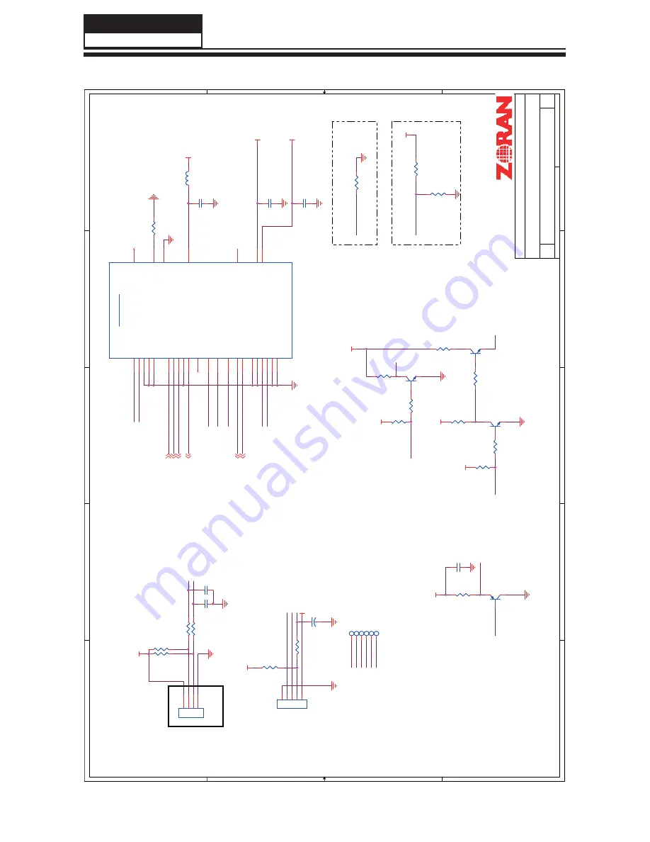
MCU I/F

A1

Zoran/HD7X5 Ref. Platform Rev 1.0

13

18

Monday, June 21, 2010

Title

Size

Document Number

Rev

Date:

S

heet

of

MCU I/F

A1

Zoran/HD7X5 Ref. Platform Rev 1.0

13

18

Monday, June 21, 2010

Title

Size

Document Number

Rev

Date:

S

heet

of

MCU I/F

A1

Zoran/HD7X5 Ref. Platform Rev 1.0

13

18

Monday, June 21, 2010

ZORAN Confidential

0: MIPS BOOTSTRAP

1: EEPROM BOOTSTRAP

0: Watchdog Timer Enabled

1: Watchdog Timer Disabled

••••••

330/0603,

••••••

5.5mA (blue)

U1.R4\R5\V3

••

GPIO

••••••••

 10.03.19

C147 0.1uF

C147 0.1uF

TP34TP34

R197

4.7K

R197

4.7K

CNE1

EJTAG6 (6pin/2.0mm)

CNE1

EJTAG6 (6pin/2.0mm)

1

1

2

2

3

3

4

4

5

5

Q13

MMBT3904

Q13

MMBT3904

CNE2 Key

CNE2 Key

1

2

3

4

TP35TP35

R202

10K

R202

10K

R201 10K

R201 10K

R194

100

R194

100

C149

47pF

C149

47pF

TP36TP36

R199

0_DNS

R199

0_DNS

R195

10K

R195

10K

MCU I/F

U1J

ZR39745

MCU I/F

U1J

ZR39745

ADC8_IN0

L1

ADC8_IN1

L2

ADC8_IN2

L3

ADC8_IN3

M2

ADC8_IN4

M3

IRR

T1

WDT_EN

P1

INT0_N/GPIO_TVP13/HDMI2_HPD

P4

INT1_N/GPIO_TVP23

P3

INT2/GPIO_TVP29

U3

T0/GPIO_TVP21/HDMI2_5VSENSE

T4

T1/GPIO_TVP24

P5

TVCPU_PWM0

M4

GPIO_TVP0/HDMI1_SCL

R4

GPIO_TVP1/HDMI1_SDA

R5

GPIO_TVP2/HDMI1_HPD

T5

GPIO_TVP3/HDMI1_5VSENSE

U4

GPIO_TVP4/HDMI2_SCL

V3

GPIO_TVP5/HDMI2_SDA

V4

POWER_CTL1

R2

POWER_CTL2

R3

BOOT_OPT

P2

VDD33_BOD

M1

COREVDD_STB

T7

IOVDD_STB

U7

VBAT

M5

CLK32K_RTC

N5

CLK25M_VDD3V3

U9

ADC8_RBIAS

L4

R204 4.7K

R204 4.7K

C144

10uF

C144

10uF

R200

330

R200

330

TP37TP37

C145 0.1uF

C145 0.1uF

R192

10

R192

10

TP38TP38

Q14

MMBT3906

Q14

MMBT3906

1

2

3

R206

1K

R206

1K

R196 330

R196 330

C148 0.1uF

C148 0.1uF

C146 0.1uF

C146 0.1uF

Q15 MMBT3904

Q15 MMBT3904

R193

10K_DNS

R193

10K_DNS

R203 4.7K

R203 4.7K

R190

10K

R190

10K

R188

15K

R188

15K

Q12 MMBT3904

Q12 MMBT3904

R205

10K

R205

10K

L23 GZ1608D601

L23 GZ1608D601

R198

10K

R198

10K

C150

0.1uF

C150

0.1uF

TP33TP33

R189 15K

R189 15K

R191

10

R191

10

  Service Manual

  Model No.: HL37XLE2

38

Содержание HL37XLE2

Страница 1: ...ice a product Products powered by electricity should be serviced or repaired only by experienced professional technicians Any attempt to service or repair the product or products dealt with in this service information by anyone else could result in serious injury or death Haier Group 2010 Qingdao Haier Electronics Co Ltd All rights reserved Unauthorized copying and distribution is a violation of l...

Страница 2: ... Read this Service Manual 7 1 4 1 Using icons 7 Chapter 2 Specification 2 1 Specification list 8 2 2 External pictures four faces 9 Chapter 3 Disassemble and Assemble 3 1 Remove the Stand 11 3 2 Remove the Back Cover 11 3 3 Remove the Adhesive Tape 11 3 4 Remove the Mainboard 11 3 5 Remove the Power Supply Modules 12 3 6 Remove the Terminal Bracket 12 3 7 Remove the Remote Control Board 12 3 8 Rem...

Страница 3: ... 7 Electrical Parts 7 1 Block Diagram 27 7 2 Circuit Diagram 28 7 2 Circuit Diagram 44 8 1 Service Mode 45 8 1 1 How to enter into Service Mode 45 8 1 2 How to exit 45 8 2 Measurements and Adjustments 45 8 2 1 Software Upgrade 45 45 See picture on the next page 45 8 2 2 Auto Color 46 8 2 3 white Balance Color Temp 47 8 2 4 Picture Mode 48 8 2 5 Audio Mode 49 8 2 6 SSPLL Setting 50 8 2 6 Aging Mode...

Страница 4: ...tant thing is to list up the potential hazard or risk for the service personnel to open the units and disassemble the units For example we need to describe properly how to avoid the possibility to get electrical shock from the live power supply or charged electrical parts even the power is off This symbol indicates that high voltage is present inside It is dangerous to make any kind of contact wit...

Страница 5: ...est 2 After removing an electrical assembly equipped with ES devices place the assembly on a conductive surface such as aluminum foil to prevent electrostatic charge buildup or exposure of the assembly 1 3 4 About lead free solder PbF This product is manufactured using lead free solder as a part of a movement within the consumer products industry at large to be environmentally responsible Lead fre...

Страница 6: ...90 99 strength CAUTION This is a flammable mixture Unless specified otherwise in this service manual lubrication of contacts is not required Capacitors may result in an explosion hazard 5 Do not defeat any plug socket B voltage interlocks with which receivers covered by this service manual might be equipped 6 Do not apply AC power to this instrument and or any of its electrical assemblies unless a...

Страница 7: ...rcuit assembly into which the device will be installed CAUTION Be sure no power is applied to the chassis or circuit and observe all other safety precautions 17 Minimize bodily motions when handling unpackaged replacement ES devices Otherwise harmless motion such as the brushing together of your clothes fabric or the lifting of your foot from a carpeted floor can generate static electricity suffic...

Страница 8: ...e but may nevertheless be valuable to the reader such as tips and tricks Caution A caution is used when there is danger that the reader through incorrect manipulation may damage equipment loose data get an unexpected result or has to restart part of a procedure Warning A warning is used when there is danger of personal injury Reference A reference guides the reader to other places in this binder o...

Страница 9: ...et Channels 181 OSD Language English Color System ATSC Audio System NTSC Audio Output Power Built in W 10W 2 Audio Output Power outer W No Total Power Input W 90W Voltage Range V 120V Power Frequency Hz 60HZ Time of Sleep Timer MINS 120Min Net Weight KG 19 69 Gross Weight KG 21 2 Net Dimension MM 910 260 644 Packaged Dimension MM 1200 255 690 Chapter 2 Specification 2 1 Specification list ...

Страница 10: ...Service Manual Model No HL37XLE2 9 2 2 External pictures four faces Front Side Left Side ...

Страница 11: ...Service Manual Model No HL37XLE2 10 Right Side Back Side ...

Страница 12: ...ith the circles in the picture above 3 Remove the stand 3 2 Remove the Back Cover 1 Remove the thirteen screws indicated See picture right 2 Then remove the back cover from the unit 3 3 Remove the Adhesive Tape The location of the adhesive tape is shown below Remove the adhesive tape Remove the four screws indicated by the red circles in the picture See next page Service Manual Model No HL37XLE2 1...

Страница 13: ...w picture Disconnected the coupler CNE3 and CNE2 Remove the remote control board 3 8 Remove the Speaker Remove the four rubber bands indicated by the red circles in below picture Take out the speakers 3 9 Remove the Stand Backstop Remove the six screws indicated by the red circles in below picture Take out the stand backstop 3 10 Remove the Indicator Light Remove the two screws indicated by red ci...

Страница 14: ...n of Controls and Components 4 1 Board Location No Parts number Description A DC1CW0E0100M Main Board 0090725996 B 0094001856A Power Board C 0094001901DA Panel 4 2 Main Board AV Board Service Manual Model No HL37XLE2 13 ...

Страница 15: ... supply unit path CN17 Pin 10 System power on standby System board will use this pin to control system power CN17 Pin 8 Control the luminance of backlight The system can generate the PWM signal to control the strength of TFT LCD Panel s backlight through this connector Pin number Signal name Description 1 5VS 5V 2 IR IN IR 3 LEDR LAMP RED 4 LEDB LAMP BLUE 5 GND GND Remote connector CNE1 Pin number...

Страница 16: ...r connector CON2 Pin number Signal name Description 1 L L 2 L L 3 R R 4 R R Other connectors CNB2 to Upgrade the program of ZORAN745 U1 AND FLASH U3 4 3 Power Supply Board Service Manual Model No HL37XLE2 15 ...

Страница 17: ...anel CON2 CON3 Pin number Signal name Pin number Signal name 1 12V 1 24V 2 12V 2 24V 3 GND 3 24V 4 12V 4 24V 5 GND 5 24V 6 GND 6 GND 7 5VSB 7 GND 8 PWM_DIMMING 8 GND 9 GND 9 GND 10 PW_ON OFF 10 GND 11 STATUS 11 NC 12 BL_ON OFF 12 BL_ON OFF CONTROL SIGNAL 13 PWM_DIMMING 14 STATUS T370HW04 V4 Service Manual Model No HL37XLE2 16 ...

Страница 18: ... 11 GND Ground 36 CH2_CLK LVDS Channel 2 Clock 12 CH1_0 LVDS Channel 1 Signal 0 37 GND Ground 13 CH1_0 LVDS Channel 1 Signal 0 38 CH2_3 LVDS Channel 2 Signal 3 14 CH1_1 LVDS Channel 1 Signal 1 39 CH2_3 LVDS Channel 2 Signal 3 15 CH1_1 LVDS Channel 1 Signal 1 40 Reserved AUO Internal Use Only 16 CH1_2 LVDS Channel 1 Signal 2 41 Reserved AUO Internal Use Only 17 CH1_2 LVDS Channel 1 Signal 2 42 GND ...

Страница 19: ...B Operating Voltage Supply 24V DC regulated 6 BLGND Ground and Current Return 7 BLGND Ground and Current Return 8 BLGND Ground and Current Return 9 BLGND Ground and Current Return 10 BLGND Ground and Current Return 11 DET BLU status detection Normal 0 0 8V L Abnormal Open collector 12 VBLON BL On Off control BL On High Open 3 3V 5 5V BL off Low 0 0 8V GND 13 VDIM Internal PWM 0 3 3V for 20 100 Dut...

Страница 20: ...enna Socket RF Coaxial Wire 75 ohm Single family Dwellings Houses Connect to wall jack for outdoor antenna Outdoor Antenna To improve the picture quality in a poor signal area please purchase a signal amplifier and install properly If the antenna needs to be split for two TV s install a 2 Way Signal Splitter in the connections To install the antenna properly please contact a professional in your a...

Страница 21: ...R owner s manual Select the input source with using the C INPUT button on the remote control and then press button to select the source press ENTER button to confirm External A V Source Setup How to connect Connect the audio and video cables from the external equipment s output jacks to the TV input jacks as shown in the figure When connecting the TV to external equipment match the jack colors Vid...

Страница 22: ...ble box refer to the figure below How to connect Use the TV s COMPOSITE COMPONENT or HDMI jack for video connections depending on your set top box connector Then make the corresponding audio connections 4 5 2 5 8 4 4 How to use Turn on the digital set top box Refer to the owner s A manual for the digital set top box Use INPUT on the remote control to select B COMPONENT VGA or HDMI source Connectin...

Страница 23: ...If the refresh rate of the VGA graphic card can not be changed change the VGA graphic card or consult the manufacturer of the VGA graphic card Note Use a DVI cable R Avoid keeping a fixed image on the TV s screen R for a long period of time The fixed image may become permanently imprinted on the screen The synchronization input form for Horizontal and R Vertical frequencies is separate Resolution ...

Страница 24: ... for the 32 TV and 1920 x 1080 for the 37 and 42 TVs Press the INPUT button to select the corresponding HDMI input source Connecting Headphones You can connect a set of headphones to your set if you wish to watch a TV program without disturbing the other people in the room 2 8 5 5 Plug a set of headphones into the 3 5mm mini jack socket on the side panel of the set Note Prolonged use of headphones...

Страница 25: ...nt to watch 3 VOL Presstoadjustthevolume IntheMENUscreen thesebuttonsserveasleft rightbuttons 4 CH Press to scan through channels To scan quickly through channels press and hold down either In the MENU screen these buttons serve as up down buttons 5 POWER Press to turn on and off theTV 6 Remote Sensor Receivers IR signals from the remote control Do not put anything near the sensor which may block ...

Страница 26: ... 5 HDMI In Connect a HDMI device to receive digital audio and uncompressed digital video 6 Video In Connect a composite video device to these jacks 7 AUDIO In Connect the audio L R cables from the composite video signal source to these jacks 8 Antenna Input Connect cable or antenna signals to theTV either directly or through your cable box 9 AUDIO Out Usetheincluded adaptertoconnecttheaudioL R cab...

Страница 27: ... in Analog mode Change the audio language in DTV mode C GUIDE Press to display the guide when you are watching analog or digital channels D CCD closed caption Select a closed caption E HDMI Press to select a device connected to the HDMI input F PC Press to select the computer connected to theVGA input G Number buttons Press to change a channel H t CVUUPO Press to select digital channels For exampl...

Страница 28: ...m Phone Out AV Out TAS5707 MP1482 ZR39745 MP1484 TUNER SPDIF AP1084 DDR2 ZR39745 USB LM1117 FLASH HDMI SWITCH LM1117 MCU_RESET PHONEJACK VCC12V_IN VCC1_1 VCC5_0 VCC1_8 VCC3_3 VCC5V_STB VCC3_3_STB Power Supply Service Manual Model No HL37XLE2 27 ...

Страница 29: ...d are 10 25V ceramic X7R 0402 form factor All inductors are listed in microhenries and are 5 non wound 0603 form factor Signal Ports and Off Page Connectors are Global and transition between sheets 5 Signal Names without Signal Ports or Off Page Connectors are Local and only connect like named signals on the same sheet Notes unless otherwise specified 1 2 3 4 All resistors are listed in ohms and a...

Страница 30: ...K R29 47K D20 ESD_0402_10pF D20 ESD_0402_10pF 1 2 D24 ESD_0402_0 15pF D24 ESD_0402_0 15pF 1 2 R58 33K R58 33K C31 10nF C31 10nF R27 47K R27 47K D29 D29 1 2 D42 ESD_0402_0 15pF D42 ESD_0402_0 15pF 1 2 D54 D54 1 2 D16 ESD_0402_0 15pF D16 ESD_0402_0 15pF 1 2 R41 47K R41 47K C32 0 1uF C32 0 1uF D52 ESD_0402_0 15pF D52 ESD_0402_0 15pF 1 2 D31 D31 1 2 CN2 HDMI_con CN2 HDMI_con SHELL1 20 SHELL2 21 D2 1 D...

Страница 31: ...1 NC 2 NC 3 VCC 4 RF_AGC 5 GND 6 SDA 7 SCL 8 AS 9 IFA_OUT 10 NC 11 IF_AGC 12 GND 17 GND 18 GND 15 GND 16 DIF1 13 DIF2 14 R66 10K R66 10K C44 1nF C44 1nF C38 0 1uF C38 0 1uF L4 10uH 300mA SMD_1005MIL L4 10uH 300mA SMD_1005MIL 1 2 L8 BLM18AG601SN1D L8 BLM18AG601SN1D C39 470uF 16V C39 470uF 16V L5 10uH 300mA_DNS SMD_1005MIL L5 10uH 300mA_DNS SMD_1005MIL 1 2 L6 BLM18AG601SN1D L6 BLM18AG601SN1D R804 0 ...

Страница 32: ...TP5 C66 0 01uF C66 0 01uF C73 3 9nF C73 3 9nF D58 ESD 0402 D58 ESD 0402 D59 ESD 0402 D59 ESD 0402 R78 0R R78 0R R88 0R_DNS R88 0R_DNS C64 10uF C64 10uF TP10 TP10 TP7 TP7 D65 ESD 0402 D65 ESD 0402 L11 47R L11 47R R81 75R R81 75R R84 3 3K R84 3 3K D61 ESD 0402 D61 ESD 0402 C67 0 1uF C67 0 1uF C65 10uF C65 10uF C59 0 1uF C59 0 1uF TP11 TP11 R89 100R R89 100R C60 1nF C60 1nF R72 75R R72 75R R82 75R R8...

Страница 33: ...ocument Number Rev Date Sheet of Component DVD A1 Zoran HD7X5 Ref Platform Rev 1 0 7 18 Monday March 22 2010 Title Size Document Number Rev Date Sheet of Component DVD A1 Zoran HD7X5 Ref Platform Rev 1 0 7 18 Monday March 22 2010 TP12 TP12 R91 75R R91 75R R92 75R R92 75R R L V CN6 RCA AV3 H1 R L V CN6 RCA AV3 H1 5 3 1 2 4 6 R93 75R R93 75R TP13 TP13 D69 ESD 0402 D69 ESD 0402 TP14 TP14 D67 ESD 0402...

Страница 34: ... 2 5 6 1 3 4 Audio IN I F U1F ZR39745 Audio IN I F U1F ZR39745 LINE_IN1_L A3 LINE_IN1_R A2 LINE_IN2_L B3 LINE_IN2_R B2 LINE_IN3_L C3 LINE_IN3_R C2 LINE_IN4_L A4 LINE_IN4_R A1 LINE_IN5_L B4 LINE_IN5_R B1 D70 ESD 0402 D70 ESD 0402 C80 1uF C80 1uF D74 ESD 0402 D74 ESD 0402 D71 ESD 0402 D71 ESD 0402 CN21 VGA R L CN21 VGA R L 1 1 2 2 3 3 4 4 5 5 6 6 7 7 R96 22K R96 22K R102 4 7K R102 4 7K TP16 TP16 HD_...

Страница 35: ...le Size Document Number Rev Date Sheet of Audio out A1 Zoran HD7X5 Ref Platform Rev 1 0 9 18 Tuesday March 23 2010 ZORAN Confidential ZORAN Confidential Close to U1 Audio OUT I F U1G ZR39745 Audio OUT I F U1G ZR39745 LINE_OUT1_L B5 LINE_OUT1_R A5 LINE_OUT2_L B6 LINE_OUT2_R A6 AC_VCM F7 AC_VREFDAC1 E6 AC_VREFDAC2 E7 AC_VREFADC F6 AC_AGNDREF G7 AC_AVDD H6 SPDIF C8 C88 0 1uF C88 0 1uF R110 1R R110 1R...

Страница 36: ... DVSS 28 PVCC_D 40 PVCC_D 41 PGND_CD 37 PGND_CD 38 OUT_D 36 OUT_C 39 PVCC_C 45 BST_C 42 VCLAMP_CD 32 BST_D 33 VREG 31 AGND 30 AVCC 34 BST_A 4 VCLAMP_AB 5 BST_B 43 PVCC_B 44 EPAD 49 PVCC 35 GND 29 OC_ADJ 7 NC 8 SSTIMER 6 R249 2K R249 2K T8 Audio_OUT T8 Audio_OUT 1 1 2 2 3 3 4 4 5 5 6 6 7 7 C465 10uF C465 10uF Q76 MMBT3904_DNS Q76 MMBT3904_DNS 1 2 3 C490 47nF C490 47nF L18 600 4 5X3 2 L18 600 4 5X3 ...

Страница 37: ...RP1B 0x4 2 7 R166 4 7K_dns R166 4 7K_dns 1 2 RP1A 0x4 RP1A 0x4 1 8 Q10 MMBT3904 Q10 MMBT3904 1 2 3 R173 4 7K R173 4 7K R171 NC R171 NC RP4B 0x4 RP4B 0x4 2 7 R176 10K R176 10K RP4A 0x4 RP4A 0x4 1 8 RP6C 0x4 RP6C 0x4 3 6 R177 10k R177 10k RP5B 0x4 RP5B 0x4 2 7 C143 4 7uF 10V_DNS C143 4 7uF 10V_DNS RP3D 0x4 RP3D 0x4 4 5 R185_DNS 10K R185_DNS 10K R168 4 7K R168 4 7K 1 2 R169 0R_DNS R169 0R_DNS 1 2 RP2...

Страница 38: ...Zoran HD7X5 Ref Platform Rev 1 0 12 18 Monday June 21 2010 Bootstrap Configuration Please note this section can not be removed GPIO1 0 GPIO0 0 from SPI boot GPIO1 0 GPIO0 1 from UART boot GPIO1 1 GPIO0 0 from NAND8 LP boot GPIO1 1 GPIO0 1 from NAND8 SP boot U1 H19 G PIO HEADPHONE_PLUG 10 03 19 U1 J21 V GA_UART_ON OFF I2S_MCLK 10 03 19 U1 H22 G ND VGA_UART_ON OFF 10 03 19 R187 4 7K R187 4 7K J3 2 5...

Страница 39: ...NE1 EJTAG6 6pin 2 0mm 1 1 2 2 3 3 4 4 5 5 Q13 MMBT3904 Q13 MMBT3904 CNE2 Key CNE2 Key 1 2 3 4 TP35 TP35 R202 10K R202 10K R201 10K R201 10K R194 100 R194 100 C149 47pF C149 47pF TP36 TP36 R199 0_DNS R199 0_DNS R195 10K R195 10K MCU I F U1J ZR39745 MCU I F U1J ZR39745 ADC8_IN0 L1 ADC8_IN1 L2 ADC8_IN2 L3 ADC8_IN3 M2 ADC8_IN4 M3 IRR T1 WDT_EN P1 INT0_N GPIO_TVP13 HDMI2_HPD P4 INT1_N GPIO_TVP23 P3 INT...

Страница 40: ...C166 0 1uF C171 0 01uF C171 0 01uF C181 1nF C181 1nF C186 0 01uF C186 0 01uF C160 10uF C160 10uF C187 1uF C187 1uF C162 1uF C162 1uF C153 1nF C153 1nF C184 0 01uF C184 0 01uF C170 1uF C170 1uF L25 GZ1608D601 L25 GZ1608D601 C152 0 1uF C152 0 1uF C178 0 01uF C178 0 01uF C192 0 01uF C192 0 01uF C167 1nF C167 1nF L28 GZ1608D601 L28 GZ1608D601 C189 10uF C189 10uF POWER U1K ZR39745 POWER U1K ZR39745 IOV...

Страница 41: ...3 GND33 M14 GND34 M15 GND35 N9 GND36 N10 GND37 N11 GND38 N12 GND39 N13 GND40 N14 GND41 N15 GND42 P9 GND43 P10 GND44 P11 GND46 P13 GND47 P14 GND49 E13 GND50 E14 GND51 Y9 GND52 Y10 GND53 Y11 GND54 Y12 GND55 Y13 GND56 Y14 GND57 Y15 L32 15uH 3A L15UH_SMD L32 15uH 3A L15UH_SMD 1 2 C204 470uF 16V C204 470uF 16V C193 1uF C193 1uF C201 0 1uF C201 0 1uF R214 27K_1 R214 27K_1 U10 MP1482 U10 MP1482 EN 7 FB 5...

Страница 42: ..._1 R219 2 7K_1 R228 180R_1 PCB Footprint R0603 R228 180R_1 PCB Footprint R0603 R224 0 R224 0 U14 LM1117MPX ADJ SOT223 U14 LM1117MPX ADJ SOT223 OUT 2 IN 3 ADJ 1 TAB 4 R215 100K R215 100K C221 100uF 16V C221 100uF 16V 1 2 R225 110R_1 PCB Footprint R0603 R225 110R_1 PCB Footprint R0603 R216 12K_1 R216 12K_1 C215 0 1uF C215 0 1uF C225 0 1uF C225 0 1uF U12 AP1084 ADJ 252 U12 AP1084 ADJ 252 OUT 2 IN 3 A...

Страница 43: ...T 1 GND 4 SS 8 COMP 6 QC LABEL LABEL2 NC QC LABEL LABEL2 NC Q20 MMBT3904 Q20 MMBT3904 1 2 3 R244 4 7K R244 4 7K C238 100uF 16V_DNS C238 100uF 16V_DNS 1 2 H12 PAD H12 PAD 1 2 3 4 5 6 R230 10K R230 10K C260 0 1uF C260 0 1uF C255 560pF C255 560pF R237 10K R237 10K H6 PAD H6 PAD 1 2 3 4 5 6 7 8 9 Q25 MMBT3904 Q25 MMBT3904 1 2 3 C261 0 1uF C261 0 1uF R231 2K R231 2K R260 0_DNS R260 0_DNS R233 4 7K R233...

Страница 44: ...e high LCD_ON GPOIs Table GPIO Pin Table Active low SPI_WEN Note USB power on off LCD_POWER_ON SPI flash protection control System power control AMP standby control GPIO_TVP24 AMP mute control AUD_AMP_MUTE AMP_STB GPIO_TVP23 POWER_CTL2 POWER_CTL1 GPIO_TVP0 ZORAN Confidential Active low Active high BL on off Active low System power control Active high Active high Active high GPIO_P6 GPIO_P14 GPIO_P...

Страница 45: ...1 CON2 CON3 CN17 CON2 CN14 CNE1 CNE2 2 2 3 CN11 37 LCD PANNEL 2 Keypad board Remote panel subassembly 1 2 2 Quantity Spec Serial NO NAME NO 5 6 7 Power wire 0090401964 LVDS wire 0090402724C Speaker wire Remote wire 0090401643B Keypad wire 0090402553A Power supply wire 0090402846A Connection wire 0090402861 1 2 3 4 Workout Auditing Standard ization Approve 0090400647K Service Manual Model No HL37XL...

Страница 46: ...1 Select the Audio menu Step 2 Input 8893 Step 3 Press the Enter button System will be into the factory mode menu when 4 steps above are done 8 1 2 How to exit If you want to exit this factory menu please press the button Exit on the remote 8 2 Measurements and Adjustments 8 2 1 Software Upgrade See picture on the next page Service Manual Model No HL37XLE2 45 ...

Страница 47: ...Color The option could only be used in the VGA and Component model When we found the color in the two models was abnormal Then we can use the function to adjust it automatically Service Manual Model No HL37XLE2 46 ...

Страница 48: ...8 2 3 white Balance Color Temp The function could adjust the Color Temperature used when debugging Service Manual Model No HL37XLE2 47 ...

Страница 49: ...8 2 4 Picture Mode Service Manual Model No HL37XLE2 48 ...

Страница 50: ...8 2 5 Audio Mode Service Manual Model No HL37XLE2 49 ...

Страница 51: ... it ON to enter the aging mode This is for factory run in testing The screen would desplay red green blue and black screen repeatedly Each color screen could be exam at that time See picture on the next page Service Manual Model No HL37XLE2 50 ...

Страница 52: ...8 2 7 Reset to default The function could make the adjustment of Service mode turn back to the factory default setting Service Manual Model No HL37XLE2 51 ...

Страница 53: ...ings to default The function could make the model turn back to the factory default setting Remark The date of the chart only is an example please don t adjust the factory mode base on it Service Manual Model No HL37XLE2 52 ...

Страница 54: ...ify if correct channel is selected Adjust the antenna Make adjustments by Fine Tune and MANUAL Scan No color for some channel program black and white Verify if the same problem exists in other channels check out of picture and sound system Refer to relative instructions in the Manual for color adjust Spots with some or all pictures Verify if the antennal is correctly connected Verify if the antenn...

Страница 55: ...t Check the input output Re soldering or change IC U13 Check the input output Re soldering or change IC U55 Check the input output Re soldering or change IC U2 Check the Speaker Change the Speaker Check the Sperker wire Fail Pass Fail Fail Fail Fail Pass Pass Pass Pass Service Manual Model No HL37XLE2 54 ...

Страница 56: ...Sunken TCP lead cracking ACF bonding short Awful environment and something electric enter into LCD Mis align between TCP and Panel Panel failure TCP failure V Dim Vertal gray line V L D Vertical color line light or dark forever H B D Horizontal bar H Dim Horizontal gary line H L D Horizontal line light or dark forever Service Manual Model No HL37XLE2 55 ...

Страница 57: ...er Bladder between Polarizer and top glass Polarizer Scratch Polarizer Scratch Tine or rigidity arose F inside Polarizer Eyewinker inside Polarizer Eyewinker inside Polarizer Circuit Abnormal Display Abnormal Display 1 Chip lose action 2 IC ahort or jointiog bad 3 Pannel and vsc connect bad Flashing Bright and dark display alternately Service Manual Model No HL37XLE2 56 ...

Страница 58: ...nt and EDS Black Screen B L normal only Black screen display FIIcker Crosstalk LCD Vcom imbalance Abnormal Color Only color abormal Capacitance improper bring crosstalk inside LCD pannel Abnormal Color Only color abnormal 1 Chip lose action 2 IC short or jointion bad 3 Pannel and vsc connect bad Service Manual Model No HL37XLE2 57 ...

Страница 59: ...wire and electrode B L dark B L brightness darker than normal Connect badnessShort between wire and electrode B L wire damaged B L wire damaged Operation abnormal or systemic noise B L wire open Without backlight Operation abnormal or systemic noise B L shut down B L shutdown in sometime Short bitween lamp housing and wire Because consume power too much F M F M inB L white balck Rotundity or wirel...

Страница 60: ...lcal or B L Light leakage Brightness at bottom of LCM brighter than normal B L unit badness Uniformity B L brightness asymmetric Sheet in B L unit is uneven Mount hole Lack screw or screw damage Lack screw Screw damage Service Manual Model No HL37XLE2 59 ...

Страница 61: ...Sincere Forever Haier Group Haier Industrial Park No 1 Haier Road 266101 Qingdao China http www haier com Printed in China ...

Страница 62: ...Service Manual Model No HL37XLE2 61 ...

Отзывы: