background image

MOUNTING

When mounting the RC-81, grasp the thermostat by the sides,
avoiding the keys, and unsnap the base from the face.  

Holding the base to the wall so that the word "TOP" is upright and
facing you:

1. Mark the two mounting holes on the wall using a pencil.  

2. Drill a hole using a 3/16" bit at each mounting hole marking. 

3. Install the two wall anchors supplied.  

4. Slide the system wires through the opening in the base.  

5. Mount the base to the wall using the two #6 x 1/2" self-tapping 

screws supplied - See Figure 1.

Figure 1 - 

Mounting thermostat base

3

Содержание Omnistat RC-81

Страница 1: ...O M N I S T A T ELECTRONIC COMMUNICATING THERMOSTAT Installation Manual RC 81 Single Stage Heat Cool Real Time Pricing System Document Number 13I00 2 January 1997...

Страница 2: ...Copyright 1997 Home Automation Inc All Rights Reserved...

Страница 3: ...1 LOCATION 2 REMOVING AN EXISTING THERMOSTAT 2 MOUNTING 3 TYPICAL WIRING DIAGRAMS 6 POWER UP 9 DISABLE KEYS 9 INSTALLER SETUP 10 OWNER S MANUAL 16 QUICK REFERENCE SETUP GUIDE 16 REMOTE SYSTEM WIRING...

Страница 4: ...1 This equipment must be installed in accordance with National wiring rules for the country in which it is installed 2 Fuses must be replaced only with IEC rated components 3 All product labels instru...

Страница 5: ...t the thermostat is located in an area where there is adequate air circulation 3 Do not mount in the path of direct sunlight or of radiant heat generated by appliances 4 Do not mount behind an outdoor...

Страница 6: ...s upright and facing you 1 Mark the two mounting holes on the wall using a pencil 2 Drill a hole using a 3 16 bit at each mounting hole marking 3 Install the two wall anchors supplied 4 Slide the syst...

Страница 7: ...at wiring If a remote system is being used with the thermostat connect the remote system wiring to the supplied cable using the wire splices per the diagram for your remote system application See Figu...

Страница 8: ...hermostat face into the thermostat base locking it into place See Figure 3 Figure 3 Mounting thermostat face to thermostat base Note Be sure that the thermostat temperature sensor is standing up and t...

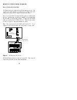
Страница 9: ...w a non replaceable fuse 3 Do not attempt to hook up to live circuits An accidental connection to a component on the thermostat circuit board could cause damage to the thermostat Figure 4 Thermostat p...

Страница 10: ...age heat only thermostat Figure 6 Single stage cool only thermostat W C Y G R FAN RELAY IF USED HEAT RELAY OR GAS VALVE COMMON TRANSFORMER CONTROL 24VAC G W C Y R FAN COOL RELAY RELAY COMMON TRANSFORM...

Страница 11: ...tivating Figure 7 Single stage heat cool thermostat Do not connect RC and RH together Figure 8 Heating cooling with separate transformers COOL RELAY RELAY FAN R Y C W G COMMON RELAY HEAT TRANSFORMER C...

Страница 12: ...he current temperature Ensure that the heater unit comes on Set the mode to OFF Ensure that the heat unit goes off 6 Set the Mode to COOL Use the down arrow key to lower the desired temperature settin...

Страница 13: ...e display are the value of the item number 3 Press the Prog key to advance to the next item 4 Press the Hold key to return to the previous item 5 Use the arrow keys to change the value of each item 6...

Страница 14: ...ode The thermostat can communicate with remote systems in 2 modes These modes are 0 300 baud RS 232 mode for use with personal computers 1 100 baud System mode Omni OmniPro and Aegis systems The defau...

Страница 15: ...format non programmable Real Time Pricing RTP Select 0 7 to disable RTP display or 8 15 to enable RTP display The default setting is 1 Add 16 to each setting to disable the clock and filter reminder...

Страница 16: ...m to refresh and dehumidify the air before the temperature rises to the desired cool setting A setting of 0 will disable this feature 0 No anticipation 3 5 Normal anticipation 10 Maximum anticipation...

Страница 17: ...ting systems a higher number will help maintain an even space temperature The default setting is 4 11 Cooling minimum on off time minutes This item is used to limit the on and off times of the cooling...

Страница 18: ...m time is sent to the thermostat every minute This adjustment will have no effect 15 Filter reminder The thermostat logs the amount of time the system fan has been running When this setting reaches 0...

Страница 19: ...ttings if any changes are made to the default settings Item Number Description Default Current 00 Address 1 01 Communication mode 1 02 System options 0 03 Display options 1 04 Calibration offset 30 05...

Страница 20: ...connected to Zone 16 and Output 8 Connect the red COMM cable wire with the black COMM cable wire Make the connections as shown in Figure 9 using the supplied wire splices Note Do not connect the red C...

Страница 21: ...ostat REMOTE is displayed when system is overriding thermostat Disconnect the cable from COMM connector to test SYMPTOM ACTION TO TAKE Can t Adjust Temperature 1 Mode is Off Select Heat Cool or Auto 2...

Страница 22: ...on to display o F or o C After installation allow the thermostat up to 30 minutes for an accurate temperature reading SYMPTOM ACTION TO TAKE Display Problem 1 Disconnect power to the thermostat Reconn...

Отзывы: