


IV.
OPERATING SYSTEMS
37
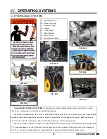
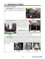
C. HYDRAULIC SYSTEM
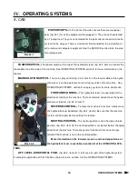
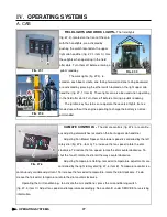
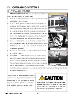
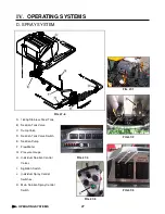
HYDRAULIC PUMPS–
The hydraulic pumps (fig. 37-1) circulate the hy-
draulic oil throughout the necessary systems and back through a cooler before
returning it to the reservoir.
If the level in the reservoir drops too low to safely operate the machine you
must shut down the engine immediately to prevent damage to the hydraulic sys-
tem.
FIG. 37-1
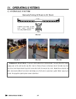
POWER STEERING SYSTEM–
The power steering is a dedicated cir-
cuit steering system with full time control, self centering/ double action steering
cylinders.
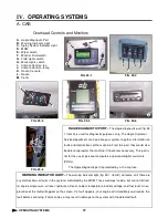
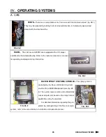
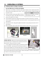
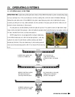
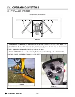
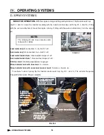
SOLUTION PUMP–
The solution pump is a centrifugal pump controlled
hydraulically with the pulse width modulated control valve. The valve is con-
trolled by the Raven console per the calibration settings entered by the operator.
The solution pump is also used to distribute the water or cleaning solution
from the rinse tank through the rinse systems.
FIG. 37-2
FIG. 37-3
OPERATING SYSTEMS
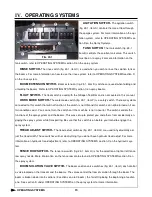
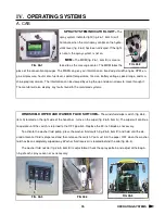
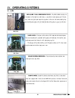
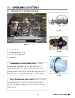
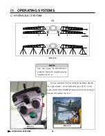
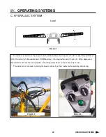
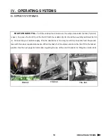
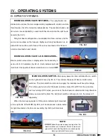
FAN CONTROL VALVE–
Both the engine fan and the auxiliary cooling fan are hydraulically controlled
through the fan control valve (fig. 37-4). The valve is located on the right side of the engine.
To reverse the rotation of both fans’ blades, depress the engine fan revers-
ing switch on the side console (fig. 37-5). The switch activates the reversing
valve (fig. 37-6). Reversing the rotation is primarily used to remove small or light
trash particles from the fan/grille screens. Continue to hold the switch until all
loose particles of trash have been removed.
*Note: the machine must be in neutral position be-
fore the fan can be reversed. The machine must remain
in neutral until the process is complete.
FIG. 37-4
FIG. 37-5
FIG. 37-6
Содержание UpFront STS 16
Страница 119: ...113 IX TROUBLE SHOOTING NOTES TROUBLE SHOOTING...
Страница 127: ...NOTES NOTES...


