background image

III. 

 SPECIFICATIONS 

3.6 

SPECIFICATIONS  

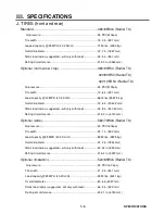
J. TIRES (front and rear) 

Standard ....................................................................... 380/85R46 (Radial TU) 


Air pressure ............................................................................. 35 PSI (240kpa) 

      Tire width .................................................................................. 15.0 in. (381 mm) 

      Loaded capacity @ 25 MPH (40.2 Km/H) ................................ 7150 lbs. (3250 kg) 

      Overall diameter ....................................................................... 72.7 in. (1847 mm) 

      Static load radius (suggested– will vary with load) ................... 33.5 in. (851 mm) 

      Rolling circumference ............................................................... 219.0 in. (5563 mm) 

Optional (narrow row crop) ........................................... 380/90R54 (Radial TU) 

                                                                                       320/90R50 (Radial TU) 

                                                                                       320/105R54 (Radial TU) 

      Air pressure .............................................................................. 35 PSI (517kpa) 

      Tire width .................................................................................. 12.6 in. (381 mm) 

      Load capacity @ 30 MPH (40.2 Km/H) .................................... 6800 lbs (5987.5 kg) 

      Overall diameter ....................................................................... 72.6 in. (2042.2 mm) 

      Static load radius (suggested– will vary with load) ................... 33.8 in. (947.42 mm) 

      Rolling circumference ............................................................... 219.0 in. (6147 mm) 

Optional (wide) ............................................................. 580/70R38 (Radial TU) 

      Air pressure .............................................................................. 23 PSI (160kpa) 

      Tire width  ................................................................................. 23.1 in. (587 mm) 

      Load capacity @25 MPH (40.2 Km/H) ..................................... 8550 lbs. (3875 kg) 

      Overall diameter ....................................................................... 72.2 in. (1834 mm) 

      Static load radius (suggested– will vary with load) ................... 32.04 in. (823 mm) 

      Rolling circumference ............................................................... 216.4 in. (5497 mm) 

Optional (floatation) ...................................................... 520/85R46 (Radial TU) 


Air pressure ............................................................................. 23 PSI (160 kpa) 

       Tire width ................................................................................. 21.3 in. (541 mm) 

       Load capacity @25 MPH (40.2Km/H) ..................................... 9350 lbs. (4241 kg) 

       Overall diameter ...................................................................... 80.6 in.(2047 mm) 

       Static load radius (suggested– will vary with load) .................. 36.3 in. (922 mm) 

       Rolling circumference .............................................................. 242.1 in. (6150 mm)  


Содержание STS 10

Страница 1: ...related accessories contain lead and lead compounds chemicals known to the State of California to cause cancer and birth defects or other reproductive harm ANY PICTURES CONTAINED WITHIN THIS OPERATOR...

Страница 2: ...MANUAL FOR HAGIE MODEL STS 10 HI TRACTOR 04 08 493411 02 09 2007 Hagie Manufacturing Company Clarion Iowa USA 721 CENTRAL AVENUE WEST BOX 273 CLARION IOWA 50525 0273 515 532 2861 COVERS MACHINE SERIA...

Страница 3: ...ATIC ID INSIDE DIAMETER IN INCH INFO INFORMATION Km H KILOMETERS PER HOUR L LITER DISPLACEMENT l LITER LIQUID LB POUND m METER MAINT MAINTENANCE MIN MINUTE M F MAINFRAME MPH MILES PER HOUR MT MOUNT MT...

Страница 4: ...condition We have attempted herein to cover all of the adjustments required to fit varying conditions However there may be times when special care must be considered Hagie Manufacturing Company reserv...

Страница 5: ...e this manual should accompany the sprayer If you do not understand any part of the manual or require additional information or service contact the Hagie Customer Support Department Hagie Manufacturin...

Страница 6: ...CIFICATIONS 3 1 3 6 IV OPERATING INFORMATION 4 1A 4 8E V CALIBRATION 5 1A 5 9B VI TRANSPORTING 6 1A 6 2C VII SERVICE AND MAINTENANCE 7 1A 7 1J VIII STORAGE 8 1 8 2 IX TROUBLE SHOOTING 9 1A 9 2E X LIMI...

Страница 7: ...CONTINUED I SAFETY DECALS DRIVING Before moving sprayer make sure no persons or obstructions are in path of travel Do not permit passengers on sprayer when it is moving they may fall off or obstruct o...

Страница 8: ...M settings Operate engine at one bump to assure proper charge pressure for brakes to work properly Start engine from operator s seat only Do not by pass safety start switch Never use starting fluid to...

Страница 9: ...o not smoke while refueling Do not fill fuel tank completely Fuel may expand and run over GENERAL REPAIR MAINTENANCE Turn off engine before checking adjusting repairing lubricating or cleaning any par...

Страница 10: ...sidue from sprayer to prevent corrosion and deterioration Select a safe area to fill flush calibrate and clean sprayer where chemicals will not drift or run off to contaminate people animals vegetatio...

Страница 11: ...replaced Following are locations of important safety de cals Replace them if they are torn or missing All warning decals and other instructional Hagie decals or machine striping may be purchased thro...

Страница 12: ...I SAFETY DECALS 1 6 SAFETY DECALS CONTINUED 650165 Right side rear cab post 650174 In engine compartment on radiator 650164 Left side rear cab post...

Страница 13: ...S 1 7 SAFETY DECALS CONTINUED 650176 Inside right hand cab post by rear window 650178 Quick attach mount On hydraulic reservoir to left of sight gauge picture 2 650339 On front cross member left side...

Страница 14: ...Y DECALS 1 8 SAFETY DECALS CONTINUED 650850 On solution tank near fill lid front fill fig 1 650848 On ladder pivot tube 650849 On engine compartment near fuel cell cap 1 2 On eductor tank lid side fil...

Страница 15: ...I SAFETY DECALS 1 9 SAFETY DECALS 650982 650981 In engine compartment near radiator cap 650851 Left rear mainframe On fuel cell near batteries Fuel cell...

Страница 16: ...hubs have identifica tion plates that describe the type of mount and gear ratio To ensure prompt efficient service when or dering parts or requesting service repairs from Hagie Manufacturing Company r...

Страница 17: ...el Hubs Left Right Front Rear Hydrostatic Pumps Refer to parts manual Front Wheel Motors Left Right Refer to parts manual Rear Wheel Motors Left w Sensor Right w Sensor Bonfiglioli Fairfield Fairfield...

Страница 18: ...Sauer Danfoss Tandem 90 series Displacement 150cc 75 X 2 with electronic displacement control Drive train All time four wheel drive Speed ranges 2 work mode 3 transport mode Hydrostatic wheel motors...

Страница 19: ...olyethylene w sight gauge Optional 1000 gal 3785 stainless steel w sight gauge Agitation polyethylene tank Eductor type w elect var speed control Agitation stainless steel tank Sparge type w elect var...

Страница 20: ...er point 1 wiper washer power point 2 XS A2 module power Norac if equipped Raven console XT2 A1 module 20 AMP 2 each power HVAC fan high 25 AMP 1 each FUSE MODULE 2 Ignition ON 5 AMP 1 each Radio dome...

Страница 21: ...AND REALYS Flasher light harness 12V flasher relay 15 AMP fuse 4 each 40 AMP relay 3 each Main rear harness 30 AMP fuse Main chassis 5V relay Console Relay 15V 100 AMP 3 Lights Front of cab 2 Trapezo...

Страница 22: ...ssure Ground speed Engine RPM Tread adjustment assist Stereo AM FM WB with CD Solution tank 1000 gallons 3785 Fuel cell 150 gallons 530 Cooling system including block lines radiator 18 gallons 68 Hydr...

Страница 23: ...lbs 5987 5 kg Overall diameter 72 6 in 2042 2 mm Static load radius suggested will vary with load 33 8 in 947 42 mm Rolling circumference 219 0 in 6147 mm Optional wide 580 70R38 Radial TU Air pressur...

Страница 24: ...tch fig 4 1A 1 item A Activate the hazard warning lights anytime day or night that you are traveling on a public road unless prohibited by law FIG 4 1A 6 A Hazard Warning light switch B Highway lights...

Страница 25: ...witch is not a self centering switch you must return it to the OFF position by hand after com pleting your turn FIG 4 2A 4 FIG 4 2A 5 HIGHWAY LIGHTS RUNNING LIGHTS The high way lights are mounted on t...

Страница 26: ...ndle is for the movement of the upper portion of the steering column only The steering wheel has infinite position possibilities To use the adjustment handle turn it down toward the operator to loosen...

Страница 27: ...Boom Extension switch I Float switch J Work Mode switch K Tread Adjust switches L Boom Spray Section switches M Fence Row Nozzle switch N Power Ports FIG 4 4A 1 A B C D O Forward P Neutral Stop Q Rev...

Страница 28: ...ture refer to OPER ATING SYSTEMS section B on the hydrostatic drive system FIG 4 5A 2 THROTTLE SWITCH The throttle switch fig 4 5A 3 is used to control engine RPM There are 2 set tings that are contro...

Страница 29: ...this switch can not be turned on if certain conditions exist You can not turn the switch on if the machine is not in neutral The switch controls the functions of the spray system and the booms This wa...

Страница 30: ...ING SYSTEMS section D on spray systems for more informa tion FORWARD CONTROL The hydrostatic lever is responsible for the direction of motion of the machine To move forward slowly move the hydro stati...

Страница 31: ...he machine From this port they would also be able to reprogram the machine if it becomes necessary This port is not for the use of personal computers or personal digital assistants PDA s The Hagie dia...

Страница 32: ...4 9A 5 item B is adjustable Check the spray pattern and adjust at the begin ning of each season or as necessary FIG 4 9A 3 A B FIG 4 9A 4 A CAB SPRAY SYSTEM INDICATOR LIGHT The spray system indicator...

Страница 33: ...nded FIG 4 10A 1 A B FIG 4 10A 2 FIG 4 10A 3 CLIMATE CONTROLS The climate controls fig 4 10A 4 are con tinuous adjusting dial switches located on the front upper cab headliner Adjusting Fan Blower Spe...

Страница 34: ...the radio manufacturer s manual for operating and programming information RAVEN SPRAY SYSTEMS CONSOLE The spray system is controlled by the Raven SCS 4600 fig 4 11A 3 and the Pulse Width Modulated Val...

Страница 35: ...irrors D Buddy Seat E Cab Fresh Air Filters F Interior Lights G Air Ride Seat FIG 4 12A 3 INTERIOR LIGHTS The STS10 cab has two interior lights A dome light that comes on when the door of the cab is o...

Страница 36: ...lass The front windshield is rounded with a green UV reflective tint and the side and back panels are flat with a UV reflective gray tint The design of the cab and the use of the glass allows a 210 vi...

Страница 37: ...ustment Pull knob out to lower seat Push knob in to raise seat C Lateral Isolator Lift lever to engage lateral isola tor Push lever down for lock out D Ride Firmness Adjustment Rotate knob coun terclo...

Страница 38: ...215hp Cummins diesel engine fig 4 1B 1 The engine has a direct mounted Sauer Danfoss 90 Series tandem hydro static pump fig 4 1B 2 More information on the operation of the en gine is on the next page...

Страница 39: ...em if needed Start engine from operator s seat only When running engine in a building be sure there is adequate ventilation 7 1B 7 3B 7 1B 7 2C 7 1C 7 3C 7 1F 7 1J NOTE Cold oil may not flow in quanti...

Страница 40: ...wait for the wait to start light in the message center fig 4 3B 3 to go out be fore engaging the starter If the engine fails to start after 15 seconds turn the key to OFF wait one minute and repeat t...

Страница 41: ...ine slowly pull the hydrostatic lever back To stop slowly push the lever to the N neutral position 5 Before turning off the engine reduce engine speed and allow the engine to idle at least three minut...

Страница 42: ...riable displacement pump that supplies the required hydraulics to operate the full time power steering unit boom control cylinders lift level and fold tread adjust ladder outer boom breakaway and the...

Страница 43: ...NG SYSTEM The power steering is a dedicated circuit steering system with full time control and self centering double ac tion steering cylinders SOLUTION PUMP The solution pump is a centrifugal pump co...

Страница 44: ...to lower ladder from the ground level ladder may swing quickly and strike an unsuspecting person FIG 4 3C 2 LADDER To raise or lower the ladder you will need to locate the BRAKE LADDER switch at the f...

Страница 45: ...Release the switch when the tread indicator reaches the desired tread marking 4 After adjustment is complete all four tread width indicators should have identical readings 5 To recalibrate toe in whi...

Страница 46: ...ches located in the sprayer s cab and hydraulic cylinders attached to the booms It provides control of lift level horizontal extension and vertical extension All STS 10 spray booms are equipped with a...

Страница 47: ...tip manufacturer s guide for information regarding spray tip height fig 4 6C 3 To raise and lower the transom boom assembly depress the square rocker on the hydrostatic lever fig 4 6C 1 and move it ei...

Страница 48: ...left or right Round Rocker UP or the left or right Round Rocker DOWN buttons on the hydrostatic lever fig 4 7C 3 While depressed these buttons activate the level cylinders connecting either boom to th...

Страница 49: ...hydrostatic lever fig 4 8C 3 While depressed these switches activate cylinders connecting either boom to the transom fig 4 8C 2 Fold or unfold the booms in an open area only Make sure no one is standi...

Страница 50: ...s will stop VERTICAL EXTENSION To fold the boom extensions vertically in or out depress the top or bottom of the Boom Extension switch fig 4 9C 2 This activates BOTH extension cylinders connecting the...

Страница 51: ...2 item A Remove the pin on the back side of the boom fig 4 10C 2 item B so it will hinge forward fig 4 10C 3 and secure it with the rear pin fig 4 10C 4 Repeat these steps on the other side and recal...

Страница 52: ...RATION PAGE REFERENCE 1 Calibrate spray system console 2 Check contents and quantity in solution tank 5 1A 5 9B or Raven manual NOTE Never attempt to operate the spray system without solution in the s...

Страница 53: ...ank Valve D Sump Valve E Solution Tank Valve Switch F Solution Pump G Flow Meter H Pressure Gauge I Individual Solution Control Valves J Agitation Switch K Individual Spray Control Switches L Main Sol...

Страница 54: ...inside the cab with the TANK VALVE switch fig 4 3D 3 located on the right hand console TANK SUMP VALVE The tank sump valve fig 4 3D 2 item 2 is a ball type valve that has to be turned on and off manua...

Страница 55: ...The pressure gauge fig 4 4D 1 gives you the operator a constant visual display of the amount of solu tion being applied measured in PSI The pressure as determined by the pulse width modulated control...

Страница 56: ...down fig 4 5D 3 and the assembly will lower fig 4 5D 4 Connect it to your solution supply fill to the desired level You may also fill the rinse tank from the ground level with the owner supplied conne...

Страница 57: ...ure 4 6D 2 below FIG 4 6D 2 F CHEM INDUC F CHEM INDUC F CHEM INDUC F CHEM INDUC TOR RINSE VALVE TOR RINSE VALVE TOR RINSE VALVE TOR RINSE VALVE CLOSE WHEN CLOSE WHEN CLOSE WHEN CLOSE WHEN NOT IN USE N...

Страница 58: ...green indicator light mounted on the right side of the MDM fig 4 7D 4 will illuminate and a white indicator light mounted on the transom assembly fig 4 7 5 will illuminate also FIG 4 7D 3 FIG 4 7D 5...

Страница 59: ...n pressure A pair of amber L E D lights mounted on the transom fig 4 7D 2 on either side of the boom solution valve indicator lights will inform the operator of fence row status If the left fence row...

Страница 60: ...ecrease lever in crease the solution pressure to maximum PSI 2 Close the solution tank valve fig 4 9D 2 3 Depress the SOLU TANK rinse switch fig 4 9D 2 item 3 4 When finished rinsing the solution tank...

Страница 61: ...n the knob on the regulator clockwise for more pressure and counterclock wise for less pressure To correctly decrease the pressure in the foam tank you must first open either the left or right foam va...

Страница 62: ...gh room for the foam con centrate Next add the foam concentrate according to the label on the container After filling is complete close the 2 ball valve on top of the tank Start the sprayer s engine a...

Страница 63: ...e the solution valves are OFF and turn off the engine be fore disconnecting any hoses or electrical lines 7 Once you have cleared the lock pin unhook the hydraulic solu tion electrical and foamer line...

Страница 64: ...partially open in order for it to stand properly Make sure that there is adequate room to allow for the boom If you are storing the boom in a building make sure that you have adequate room around it...

Страница 65: ...s The stands are very simple They are a brackets attached to the end of the first boom section on both booms and two on the transom Each has a leg with a foot on the bottom Each has a hex bolt in the...

Страница 66: ...t section is even with the rear of the cab fig 4 4E 1 This position will allow the booms to sit level with the transom without causing too much stress on the either part It will also keep the weight f...

Страница 67: ...zle solution on the right side fig 4 5E 3 item 1 and the main solution disconnect on the right side of the machine above the front wheel fig 4 5E 4 If you have the foamer option there are two hoses ne...

Страница 68: ...connecting any hoses or electrical lines 5 Re attach all solution lines electrical lines hydraulic lines and foamer lines if equipped If you are attaching to something other than the boom be sure you...

Страница 69: ...ir out of the air bags using the relief valves If your machine is not equipped with the valves you will need to call Hagie Customer Service and pur chase airbag relief valve kits and install them on t...

Страница 70: ...begins to support the boom BOOM STANDS This would also be a good time to put the boom stands if equipped in travel position by removing the pin and sliding the leg all the way up Re insert the pin ab...

Страница 71: ...op it is being use on The size of nozzles selected will be based upon the speed the sprayer will travel the nozzle spacing and the number of gallons one intends to apply per acre TIP SELECTION There a...

Страница 72: ...should have a successful chemical application These calculations are based on a 20 spacing refer to the Spray Products catalog for the formula for choosing a spac ing other than 20 NOZZLE SIZE PSI DR...

Страница 73: ...turned off 3 If any error is made during the programming of the area measurement standard or the valve type turn the console OFF Depress CE and hold while turning the console power ON IMPORTANT The i...

Страница 74: ...splay will display Initial Contrast Adjust ment The display will show ACRE US HECTARE SI OR TURF SQ FEET Depress until PWM VALVE is displayed Momentarily depress to select CE Enter The display will no...

Страница 75: ...ons before entering this calibration Pay attention to the placement of the decimal point The decimal point can be shifted for greater accuracy but if in the wrong place can cause great disaster Enter...

Страница 76: ...initial programming of the console Refer to the Raven manual for more information The speed that is displayed on the Raven console if the console is programmed correctly and the SPEED CAL is refined...

Страница 77: ...they control the spacing option in stalled and the number of nozzles per section The diagram below shows a dry boom option See the next page for a wet boom option diagram The boom is numbered from le...

Страница 78: ...SHOOTING 60 80 90 foot boom system with all extensions folded out 90 feet BOOM 1 BOOM 2 BOOM 3 BOOM 4 BOOM 5 The difference between the dry boom previous page and the wet boom is that the dry boom s...

Страница 79: ...is indicates the slowest rate in which the solution valve will function Enter The initial programming is now complete You may have to refine some of the numbers to better suit your unique situation Th...

Страница 80: ...tion for at least 10 minutes for proper warm up of the sprayer and its system Once the system has had an adequate warm up period you will need to perform a self test to simulate speed although the mac...

Страница 81: ...IDE REFER TO THE RAVEN INSTALLATION AND OPERATION MANUAL FOR MORE INFORMATION AND TROUBLE SHOOTING Performing a SELF TEST Depress to perform a SELF TEST SELF TEST 8 Depress to select Enter the speed t...

Страница 82: ...ions in raise the transom and fold the booms in toward the machine When the boom reaches the last 8 10 degrees of travel it will automatically slow down to avoid im pact with the cradle Raise each ind...

Страница 83: ...t drive under trees bridges wires or other obstructions unless there is clearance 9 Use extra care before entering or leaving a public road or highway 10 A SMV Slow Moving Vehicle emblem has been moun...

Страница 84: ...le for turning 6 Secure the sprayer to the trailer See the trailer s owner and operator manual for instructions 7 Cover or remove the SMV Slow Moving Vehicle emblem when traveling over 25 miles per ho...

Страница 85: ...ler from moving 2 Lower the trailer ramps and set the ramp spacing to the sprayer s tread setting 3 Release the securing restraints carefully 4 Get someone to help guide you off the trailer Keep every...

Страница 86: ...E STRAINER AS REQ DAILY 7 2B WHEEL HUB OIL LEVEL F 100HRS 7 1I WET TANK AIR TANK A 7 1D FRONT LEG STRG ZERKS 2 1EA LEG 50HRS 7 1D ALL OTHER GREASE ZERKS 19 PLACES 50HRS 7 2G TREAD ADJUSTMENT BEARING T...

Страница 87: ...7 Check solution line strainer page 7 3C 8 Drain wet tank and air tank page 7 1I 9 Check batteries page 7 1E 10 Check radiator grille screen 7 2C HOURS 10 Initial checks after receiving machine IMMED...

Страница 88: ...on line strainer page 7 4C 9 Change batteries page 7 1E 10 Change paper cab filter page 7 4C 11 Change charcoal cab filter page7 4C 12 Check and replace spray nozzle diaphragms and spray tip page 7 1J...

Страница 89: ...fuel filter water separator page 7 3C 3 Change hydraulic reservoir oil page 7 1B 4 Change wheel hub oil page 7 2B 5 Check spray nozzle diaphragms and spray tips page 7 1J 6 Change engine oil page 7 1...

Страница 90: ...l level Add hydraulic oil Solution line strainer Remove and clean Batteries Clean and or tighten Radiator grille screen Clean Look for loose or missing items such as shields Tighten or replace Look fo...

Страница 91: ...cking the oil level to make sure the measurement is correct HYDRAULIC OIL RESERVIOR OIL LEVEL Check the sight gauge level on the hydraulic oil reservoir fig 7 1B 2 daily Add just enough fluid so the l...

Страница 92: ...l at all times Less than that would limit lubrication and over that would cause overheating and damage To check the oil level position the hub so that there is a plug at the 12 O clock position fig 7...

Страница 93: ...e 7 3B 2 gives a few examples of ethyl ene glycol antifreeze water mixture protection values Consult the engine manufacturer s handbook for further information Concentration should be checked every 50...

Страница 94: ...pan including filter 17 quarts SAE 15W 40 Engine oil dipstick L H mark 2 quarts Hydraulic oil reservoir 32 gallons anti wear hydraulic oil Hydraulic system reservoir lines filter cooler etc 55 gallon...

Страница 95: ...t appropriate service time install the new element carefully to ensure proper sealing CLEANING It is not recommended to clean the air intake filter element However a clean damp cloth should be used to...

Страница 96: ...the radiator oil cooler or A C condenser with compressed air or water be careful not to damage cooling fins which may impair cooling capabilities HYDRAULIC FILTER AND STRAINERS RETURN FLITER Remove an...

Страница 97: ...rection of the fuel flow arrow when replacing PRIMARY FUEL FILTER WATER SEPERATOR fig 7 3C 4 Located on the right side of the engine this filter should be drained daily of the water and other deposits...

Страница 98: ...ine strainer screen Confirm the gasket is in place before re installing the screen Check all strainers occasionally for blockage and replace them if they show signs of deterioration Refer to the Hagie...

Страница 99: ...eased every 50 hours depending on the amount of usage Each leg also has a grease zerk on the inside of the leg fig 7 1D 2 that should be greased every 50 hours Tall crops may wipe away much of the gre...

Страница 100: ...n the rear of the sprayer s mainframe fig 7 1E 2 Connect your charging cables to them just as you would to the battery positive cable to positive terminal and negative cable to negative terminal Keep...

Страница 101: ...EAKERS FUSES The STS 10 has circuit breaker and fuse systems in various locations Under the right hand console fig 7 2E 1 for the cab functions under the cab fig 7 2E 2 for the light func tions and th...

Страница 102: ...idth cracks are ac ceptable Longitudinal direction of the belt length cracks that intersect with transverse cracks are not accept able Replace the belt if it is frayed or has pieces of material missin...

Страница 103: ...sequence in figure 7 1G 3 first turn each lug nut to a torque value of 120 dry foot pounds Use slow even pressure on the torque wrench Quick or jerky movements cause inaccurate values Repeat the same...

Страница 104: ...axle and still allow tread width adjustment Even pressure of the tread adjust bearing plates is required for proper operation fig 7 2G 3 Figure A shows the correct position of the tread adjust bearin...

Страница 105: ...ll between one half and three quarters of an inch Toe in is preset at the factory and should not have to be adjusted unless the steering cylinders are re moved Difficulty steering one way versus the o...

Страница 106: ...til the measurement from the center of the rod end to the collar fig 7 2H 1 item 2 is the same on both of the front steering cylinders 4 Tighten jam nut 5 Phase cylinders again re check toe in measure...

Страница 107: ...leasing the drain cock Check for moisture in the system If there is excessive moisture in this tank there may be a problem with the sys tem Call Hagie Customer Support for assistance FIG 7 1I 3 Pull d...

Страница 108: ...and inspect the nozzle tips If they are plugged or worn clean or replace them DO NOT put your mouth to a spray tip to try to unplug it NOZZLE DIAPHRAGMS At the beginning of each season remove each no...

Страница 109: ...store the batteries in a cool above freezing place 9 Thoroughly clean the sprayer Touch up any painted surfaces that are scratched or chipped For touch up paint recommendations contact the Hagie Manuf...

Страница 110: ...ngine oil hydraulic oil and engine coolant levels add if necessary A mixture of 50 50 anti freeze and water will cool adequately in summer as well as protect in winter 6 Completely clean the sprayer 7...

Страница 111: ...fuse Turn battery switch to ON posi tion Engine won t start Out of fuel Clogged fuel filter Cold weather Low starter speed Blown fuse in engine electric box Fill fuel tank Replace fuel filters Refer...

Страница 112: ...Drain flush replace filter fill system Replace element Drain system change to a bet ter grade fuel Open fuel tank vent in cap Replace fuel filter Engine knocks Low oil level in crankcase Cold engine...

Страница 113: ...uction line Open solution tank valve allow air to leave the system Erratic reading on pressure gauge Orifice in back of gauge clogged Faulty gauge Air leak in suction line Glycerin leaking from gauge...

Страница 114: ...tricted solution flow to pump Suction hose collapsed Internal restriction of diaphragm such as build up of chemical Hydraulic failure Remove screen clean thor oughly tighten strainer cap to avoid air...

Страница 115: ...set too low Engine speed too low Oil level in reservoir too low Clogged filter Hydrostatic system failure Adjust the setting of the speed control knob Set engine at operating RPM before trying to mov...

Страница 116: ...suction line Hydrostatic system failure Set engine at operating RPM before trying to move machine Fill reservoir to proper level with approved oil see section on service and maintenance Allow adequat...

Страница 117: ...per level with approved oil see section on service and maintenance Call Hagie Customer Service Noisy hydraulic pump Oil level in reservoir too low Auxiliary hydraulic system fail ure Fill reservoir to...

Страница 118: ...ttery connection Low charging rate No charging rate Battery master switch is in OFF position Replace battery Clean and tighten battery con nections Tighten alternator belt Replace alternator Turn batt...

Страница 119: ...9 9 IX TROUBLE SHOOTING NOTES...

Страница 120: ...ghts which may vary from state to state b Hagie makes this warranty only to the original purchaser of its new equipment c The warranty period ends 12 months from the date of delivery of equipment to t...

Страница 121: ...Coolant 7 3B Radiator Grille Screen 7 2C D Decals Location 1 5 1 9 E Electrical System 7 1E 7 2E Batteries 7 1E Charging Auxiliary Posts 7 1E Service Access 7 1E A ACE Automatically Controlled Engine...

Страница 122: ...cifications 3 2 Switch 4 7A System Pressure Gauge 4 10D Foamer Switch 4 7A Forward Control 4 7A Fresh Air Cab Filters 7 4C Front Console 4 1A 4 3A Hazard Warning Lights 4 1A Highway Lights Running Lig...

Страница 123: ...tor Light 4 9A Speed Control 4 5A Steering Column Release Pedal 4 3A Tank Switch 4 6A Throttle Switch 4 5A Tilt Adjust Handle 4 3A Tread Adjust Switches 4 6A Turn Signals 4 2A Vents 4 11A Warning Indi...

Страница 124: ...Hydraulic Pump 4 2C Hydraulic Tread Adjust 4 4C Ladder 4 3C Manually Folding Boom 4 10C Level 4 7C Lift 4 6C Power Steering System 4 2C Solution Pump 4 2C Spray Booms 4 5C Vertical extension Fold 4 9C...

Страница 125: ...1A 7 1J Service Point Quick Reference 7 1A Intervals 7 2A 7 5A Solution Line Strainer 7 4C Solution Pressure Gauge 4 4D Solution Pump 4 2C 4 3D Solution Quick Fill 4 5D Solution Tank 4 3D Solution Tan...

Страница 126: ...et Tank 7 1I Wheel Lug Nuts 7 1G Wheel Hubs 4 1B Maintenance Oil 7 2B Torque Value 7 1G Specifications 3 1 Wheel Motors 4 1B Specifications 3 1 Windshield Washer Wiper 4 9A Fluid 7 4B X Y Z 2007 Hagie...

Страница 127: ...NOTES NOTES...

Отзывы: