1
6LE000377A
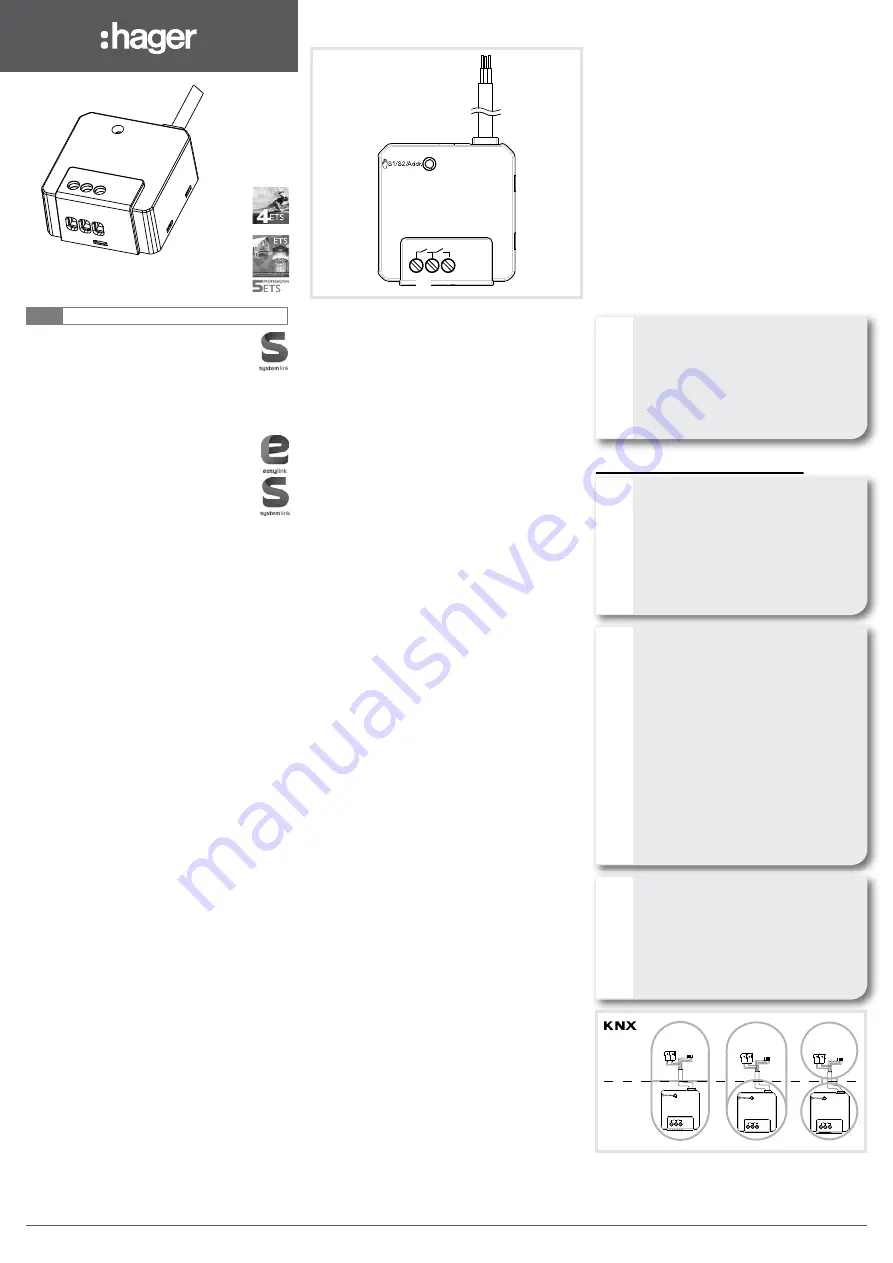
TYB6.2F
Output 2gang 6A / 1gang shutter/blind,
flush mounted
Input 2gang + output 2gang 6A / 1gang
shutter/blind, flush mounted
TXB6.2F
Output 2gang 6A / 1gang shutter/blind,
flush mounted
Input 2gang + output 2gang 6A / 1gang
shutter/blind, flush mounted
z
07/2014 - 6LE000377A
Hager Controls S.A.S., 33 rue Saint-Nicolas, B.P. 10140, 67703 SAVERNE CEDEX, France - www.hager.com
Bn,.:
M
`
Safety instructions
Electrical equipment may only be installed and
assembled by a qualified electrician in accor-
dance with the relevant installation standards,
guidelines, regulations, directives, safety and
accident prevention regulations of the country.
Failure to comply with these installation in-
structions may result in damage to the device,
fire or other hazards.
Hazard due to electric shock. Disconnect be-
fore working on the device or load. Take into
account all circuit breakers that supply
dangerous voltages to the device or load.
Hazard due to electric shock. The device is not
suited for safe disconnection of the mains sup-
ply.
Hazard due to electric shock on the SELV or
PELV installation. Do not connect any loads for
low voltage SELV, PELV or FELV together.
Connect one motor only. If several motors are
connected, motors or device might be destro-
yed.
Use drives with mechanical or electrical final
position switches only. Check final position
switches for correct adjustment. Observe
motor manufacturer‘s data. The device can be
damaged.
Observe the motor manufacturer‘s data
regarding change-over time and max. switch-
on time (ED).
These instructions are an integral component
of the product and must be retained by the end
user.
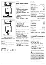
Design and layout of the device
S1 S2
KNX+ /RD
KNX- /BK
In 1 /GN
Com /WH
In 2 /YE
(1)
(2)
(3)
Fig. 1: example device variant with inputs
(1) Illuminated button for manual operation/
programming button
(2) Connection of load(s)
(3) KNX bus connection cable/
connection inputs
Function
System information
This device is a product of KNX system and corre-
sponds to the KNX guidelines. Detailed specialised
knowledge obtained from KNX training courses is
required for understanding. The planning, installa-
tion and commissioning of the device is carried out
with the help of KNX-certified software.
Systemlink commissioning
The function of the device is software-dependent.
The software is to be taken from the product
database. You can find the latest version of the
product database, technical descriptions as well as
conversion and additional support programmes on
our website.
Easylink commissioning
The function of the device is configuration-depen-
dent. The configuration can also be done using
devices developed specially for simple setting and
start-up.
This type of configuration is only possible with
devices of the easylink system. Easylink stands for
easy, visually supported start-up. Preconfigured
standard functions are assigned to the in/outputs
by means of a service module.
Functional description
The device receives telegrams from sensors or
other controllers via the KNX installation bus and
switches electrical loads with its relay contact.
Correct use
- Switching of electrical loads AC 230 V with po-
tential-free contact.
- Switching electrically operated motors of 230 V
AC for blinds, shutters, awnings and similar
hangings.
- Installation into wall box according to DIN
49073 (use deep box) or junction box surface-
mounted/flush-mounted.
Product characteristics
- Manual activation of the outputs on the device
possible, building site operation.
- Status display of the outputs on the device.
- Scene function.
- Forced position by higher-level controller.
Functions in switch operation
- Time switching functions.
Functions in roller shutter/blind operation
- Position can be started directly.
- Slat position directly controllable.
- Feedback of operating state, shutter position
and slat adjustment.
- 3 Alarms.
Functions of the inputs
- ON/OFF.
- Dimming.
- Up/down.
- Slat angle/Stop.
- Alarm.
- Scene.
- Mandatory control.
- Time switching operation.
Information for electricians
Installation and electrical connection
DANGER!
Touching live parts can result in an
electric shock!
An electric shock can be lethal!
Disconnect the connecting cables
before working on the device and
cover all live parts in the area!
ç
Connecting and installing the device
CAUTION!
Impermissible heating if the load of
the device is too high!
The device and the connected cables
may get damaged in the connection
area!
Do not exceed the maximum current
carrying capacity!
ç
CAUTION!
When connecting the bus/extension
units and mains voltage wires in a
common wall box, the KNX bus cable
might come into contact with the
mains voltage.
The safety of the entire KNX
installation is at risk. Persons could
also get an electric shock even on
remote devices.
Do not place bus/extension units and
mains voltage terminals in a common
terminal compartment. Use a wall box
with a firm partition or separate boxes
(Figure 2).
ç
CAUTION!
Risk of destruction if parallel circuit of
several motors!
Final position switches could fuse
together. Motors, hangings and the
device may be destroyed!
Connect one motor only!
ç
S1 S2
KNX+ /RD
KNX- /BK
In 1 /GN
Com /WH
In 2 /YE
S1 S2
KNX+ /RD
KNX- /BK
In 1 /GN
Com /WH
In 2 /YE
S1 S2
KNX+ /RD
KNX- /BK
In 1 /GN
Com /WH
In 2 /YE
SELV
FELV
230 V AC
Figure 2: installation with separate terminal com-
partment
S1 S2
KNX+ /RD
KNX- /BK
In 1 /GN
Com /WH
In 2 /YE
Bus
30 V DC
L
N
10 A
In 1
In 2
Com
Figure 3: connection of switching loads
S1 S2
KNX+ /RD
KNX- /BK
In 1 /GN
Com /WH
In 2 /YE
Bus
30 V DC
L
N
10 A
In 1
In 2
Com
Figure 4: connection of motors
Observe installation regulations for SELV voltage.
Maintain a minimum distance of 4 mm between
mains voltage and bus wires.
The installation circuit must be protected via circuit
breaker 10 A.
Do not connect different phases (outer conductors)
to the device.
z
Connect bus cable via connecting terminal.
z
Connect loads (figure 3/4) to the load connec-
ting terminals (2).
z
Place device into the installation box.
Connect inputs
green
white
yellow
red
black
In 1
Com
In 2
KNX+
KNX-
Table 1: connection assignment of the control line
z
Connect potential-free contacts to the inputs.
Start-up
Systemlink: loading physical address and
application software
z
Switch on bus voltage.
z
Press programming button (1).
The button lights up.
If the button does not light up, no bus voltage is
present.
z
Load the physical address into the device.
Status LED of the button goes out.
z
Load application software.
z
Note down the physical address on the device.
Easylink
Information on the system configuration can be
taken from the extensive description of the service
module Easylink.
Start up the device
z
Switch on mains voltage on the outputs.
Switch test mode on/off
The device is connected. Bus voltage and swit-
ching voltage are present.
z
Keep button (1) pressed > 5 s with a pointed
object until it flashes green.
The device is in test mode.
Or with test mode switched on
z
Keep button (1) pressed > 5 s until it flashes
green 3 times.
The device is in normal operation.
After approx. 5 min. without any further operati-
on, the device exits test mode automatically.
Operating output in test mode
Operation takes place by briefly pressing a button
repeatedly (1).
The device is in test mode. The button flashes
green until the first operation.
z
Press the button (1) for a short time.
The output changes its switching state.
The switching takes place according to the
following sequence:
S1 closed - S1 open - S2 closed - S2 open.
Resetting the device to the factory settings
z
The device provides the possibility of restoring
the factory setting via a programming button.
The programming is lost after resetting to the
factory setting. Activation via the bus is no
longer possible.
z
Hold down the button (1) for (> 10 s) until it
flashes red.
P
P
P
P
Appendix
Technical data
Supply voltage KNX
21…32 V DC SELV
Breaking capacity
µ 6 A AC1 230 V~
Switching current at cos Φ = 0.8
max. 6 A
Minimum switching current
10 mA
Operating altitude
max. 2000 m
Degree of contamination
2
Surge voltage
4 kV
Degree of protection of housing
IP20
Impact protection
IK 04
Overvoltage class
III
Operating temperature
-5°C…+45°C
Storage/transport temperature
-20°C … +70°C
Maximum switching cycle rate
at full load
20 switching cycle/minute
Connection capacity
0.75 mm²…2.5 mm²
max. tightening torque
0.5 Nm
Cross-head design
PZ1
Installation type flush-mounted installation switch/
flush-mounted electronic/
flush-mounted/surface-mounted junction box
Standards
EN 50491-3 ; EN 60669-2-1
Dimensions
44 x 43 x 22.5 mm
Own consumption on the KNX bus:
typical
7 mA
in standby
5 mA
Incandescent lamps
500 W
HV halogen lamps
500 W
Conventional transformer
500 VA
Electronic transformer
500 W
Fluorescent lamps
- without ballast
500 W
- with electronic ballast
6 x 48 W
Energy-saving lamps
5 x 13 W
LED lamps
5 x 13 W
Change-over time for
change of direction
software-dependent
Variant with inputs
Number of inputs
2
Input type
potential-free
Total length of extension unit cable
max. 9.9 m
Scanning voltage
extension unit inputs
12 V DC/1mA
Troubleshooting
Test mode not possible. Red programming LED
lights up.
Cause: push-button (1) was pressed too short.
Short press on push-button, red LED goes out.
Press push-button again (> 5 s).
Bus operation is not possible
Cause 1: bus voltage is not present.
Check bus connection terminal for correct
polarity.
Check bus voltage by briefly pressing the pro-
gramming button (1), red LED lights up if bus
voltage is present.
Cause 2: device was reset to the factory setting.
Repeat programming and start-up.
z
z
230 V
v
230 V
v
z
6LE000377C
1
6LE000377C
v


