background image

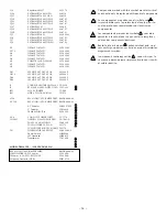
Components marked with this symbol are safety critical
and should only be replaced with identical components.

Los componentes marcados con el simbolo son
imprescindibles para la protección del equipo, por lo
cual que solo sean reemplazados por los mismos 
componentes.

Les componsants marqués du symbole       sont indis-
pensables à la sécuritée et ne peuvent être remplacés
qu'avec des composants identiques.

Bauteile, die mit einem        gekenzeichnet sind, sind
sehr wichtig und dürfen nur mit den orginal Ersatzteilen
ausgetauscht werden.

I componenti contrassegnati da        sono critici per la
sicurezza e devono essere rimpiazzati solo con ricambi
di valore identico.

– 18 –

Q3

Regulator LM337

SS-1376

Q30

XSTR MMBT5088L NPN

SS-0114

Q31

XSTR MMBT5088L NPN

SS-0114

Q32

XSTR MMBT3906LT1 PNP

SS-0791

Q33

XSTR MMBT3906LT1 PNP

SS-0791

Q35

XSTR MMBT3906LT1 PNP

SS-0791

Q37

XSTR MPS6521

SS-209

Q38

XSTR MMBT3906LT1 PNP

SS-0791

Q39

XSTR MMBT3906LT1 PNP

SS-0791

Q5

XSTR MMBTA06L

SS-102SM

Q6

XSTR MMBT3906LT1 PNP

SS-0791

Q7

XSTR MMBT3906LT1 PNP

SS-0791

Q8

XSTR MMBT3904LT1 NPN

SS-0792

U1

OPAMP TL072CD

SS-143SM

U112

OPAMP TL072CD

SS-143SM

U2

OPAMP TL072CD

SS-143SM

U3

OPAMP TL072CD

SS-143SM

U4

OPAMP TL072CD

SS-143SM

U5

COMPTR QUAD LM339

SS-730SM

U7

OPAMP TL072CD

SS-143SM

U8

OPAMP TL072CD

SS-143SM

DS1

SW SIDE ACT DIP 4 POS

SW-1649

DS12

SW SIDE ACT DIP 4 POS

SW-1649

DS4

SW SIDE ACT DIP 4 POS

SW-1649

DS8

SW SIDE ACT DIP 4 POS

SW-1649

J1

CONN XLR NEUTRIK NC3FAH-2-0 CC-2339

J2

RCA JACK, SINGLE WHITE, GOLD CCH-232

JW1

SH 2X3 JUMPER

CC-648

JW1

HDR 6 PIN DUAL ROW 

CC-673

V120

RES 0 OHM 1/4W (JUMPER WIRE) RMP/4-0000-03

VV120

RES 0 OHM 1/4W (JUMPER WIRE) RMP/4-0000-03

6.5" Woofer

FG26387WP

1" Tweeter

SPK10424

TRM6 MEHSA Bar

WP-2439

AC6

CONN IEC POWER INLET

CC-1174

CHASS1

HARNESS P1000 CHASSIS GND

FA-1401-A

FUSE 3A 3AG SLO BLO

FS-003SB

FUSE HOLDER CAP 3AG

FS-1175

FUSE HOLDER BODY PC MOUNT FS-1176

TS1

THERMISTOR 10K EPOXY

SS-0426-066

Power Switch

SHW9840

IEC Linecord

WIR9856

Transformer

TT-2326-E

MODEL: TRM6.1CE     (230 VAC 50/60 Hz)

RES 0 OHM 1/4W (JUMPER WIRE)

RMP/4-0000-03

FUSEHOLDER CAP 5X20mm

FS-1269-A

5X20mm  0.8A SLO-BLO FUSE

FS-1484-A

European Linecord <HAR>

WIR10138

Содержание TRM6.1

Страница 1: ......

Страница 2: ...S A Importer s Name ________________________________________________________ Importer s Address ________________________________________________________ Type of Equipment 2 channel Audio Power Amplif...

Страница 3: ...TC 20Hz 20kHz 0 1 THD 35 Watts RMS 6 ohms high frequency 50 Watts RMS 4 ohms low frequency Signal to Noise 100dB CMRR 70dB typical 1kHz Input Impedance 47k per phase balanced 47k unbalanced Input Sens...

Страница 4: ...f the equip ment s plug be able to fully insert into the mating receptacle Never remove the round grounding pin on the plug in an attempt to mate to a two wire ungrounded receptacle use a grounding ad...

Страница 5: ...rioente requerida pra la operaci n segura de todo el equipo conectado Aun m s las extensiones deben proveer de la misma conecci n aterrada de tres hiles Es importante que el enchufe se pueda introduci...

Страница 6: ...rt des util isations de ce mat riel L utilisation de rallonge t d adaptateur est d consell e moins d tre en mesure de fournir la charge lectrique requise un fonctionement sans risque de tout mat riel...

Страница 7: ...isten Anwendungen v l lig ausreicht Wenn Sie Verl ngerungskabel benutzen achten Sie darauf das dies die erforderlichen Str me bertragen k nnen Benutzen Sie immer dreiadrige Verl ngerungskable 11 ZEITR...

Страница 8: ...i impieghi L impiego di prolunghe e adattatori sconsigliato se questi non garantiscono la potenza sufficiente per i corretto fuinzionamento degli apparati connessi E alters importante che vengano semp...

Страница 9: ...matic Diagram 7 PC Board Layout 12 OPERATION Input Sensitivity 13 Bass Roll Off 13 Bass Shelving 14 Treble Shelving 14 AC Line 14 Power Switch 14 Status LED 15 Rubber Pad 15 Break In and Warm Up 15 Cl...

Страница 10: ...r The high frequency channel features up to 4dB of Treble shelving while the low frequency channel features up to 4dB of Bass shelving In addition the low frequency channel includes an active 2nd orde...

Страница 11: ...y an active node formed by the driver transistors at ultrasonic frequencies This allows amplifier performance similar to Trans nova which is highly stable and linear while utilizing the advantages of...

Страница 12: ...his type of shielding prevents color and image distortion when placing the woofer in close proximity to direct view CRT television receivers and computer monitors THE RESULT Prevents distortion in TV...

Страница 13: ...nt Panel View 4 Rear Panel View Woofer Tweeter Rubber Pad Status LED Wave Guide Heatsink AC Line Input AC Line Fuse Balanced Input Unbalanced Input Sensitivity Bass Roll Off Bass Shelving Treble Shelv...

Страница 14: ...TION Aiming the monitors directly forward Fig 1 may cause response problems resulting in inadequate stereo imaging Aiming the monitors toward you and spaced equally like a triangle Fig 2 provides the...

Страница 15: ...noise INPUT SWITCH The unbalanced input uses a conventional RCA phone jack Move the input switch ON to use this jack The balanced input jack is an XLR plug The XLR jack is connected according to the I...

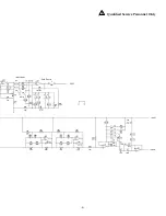
Страница 16: ...SCHEMATIC DIAGRAM NOTES Unless specified otherwise 1 All resistors in ohms 2 All capacitors in microfarads 3 Channel 1 only shown 7...

Страница 17: ...Qualified Service Personnel Only 8...

Страница 18: ...SCHEMATIC DIAGRAM NOTES Unless specified otherwise 1 All resistors in ohms 2 All capacitors in microfarads 3 Channel 1 only shown 9...

Страница 19: ...Qualified Service Personnel Only 10...

Страница 20: ...11 S CHEMATIC Diagram NOTES Unless specified otherwise 1 All resistors in ohms 2 All capacitors in microfarads 3 Channel 1 only shown Qualified Service Personnel Only...

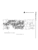
Страница 21: ...PC B OARD L AYOUT Qualified Service Personnel Only 12...

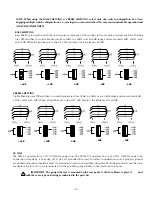
Страница 22: ...Y select only one switch configuration at a time Engaging multiple switch configurations i e moving two or more switches ON may cause undesirable operation and is NOT RECOMMENDED I N P U T 11dB Input...

Страница 23: ...equencies from 5kHz to 20kHz over an 8dB range and are marked 4dB 2dB 2dB and 4dB When all switches are in the OFF left position the treble level is at 0dB 14 2dB 4dB 2dB 0dB 4dB 2dB 4dB 2dB 0dB 4dB A...

Страница 24: ...ED Amplifier operation is monitored internally and has a status LED This indicator can be used for system troubleshooting in case of aberrant behavior RUBBER PAD A large rubber pad is supplied to elim...

Страница 25: ...1 10W 1 RM 10 2001B R172 RES 2 0K OHM 1 10W 1 RM 10 2001B R173 RES 2 21K OHM 1 10W 1 RM 10 2211B R174 RES 1 33K OHM 1 4W 1 RM 4 1331C R175 35 7K OHM 1 10 WATT 1 RM 10 3572B R176 RES 909 OHM 1 10W 1 RM...

Страница 26: ...C44 CAP 220PF 50V 5 CDS 221CAAA C45 CAP 01UF 50V CYV 103 033 C46 CAP 01UF 50V CYV 103 033 C47 CAP 001UF 50V CYV 102 033 C48 CAP 001UF 50V CYV 102 033 C49 CAP 220PF 50V 5 CDS 221CAAA C5 047UF 50V CYV 4...

Страница 27: ...T3906LT1 PNP SS 0791 Q7 XSTR MMBT3906LT1 PNP SS 0791 Q8 XSTR MMBT3904LT1 NPN SS 0792 U1 OPAMP TL072CD SS 143SM U112 OPAMP TL072CD SS 143SM U2 OPAMP TL072CD SS 143SM U3 OPAMP TL072CD SS 143SM U4 OPAMP...

Страница 28: ...TRM6 1 FUNCTIONAL BLOCK DIAGRAM 19...

Страница 29: ...nt end drive current and drive the positive output MOSFET Q20 The same is true for buffer transistors Q31 and Q33 and negative output MOSFET Q4 CALIBRATION WARNING Only a competent technician should a...

Страница 30: ...gnal from U1A pin 1 and the inverting input signal from U1B pin 7 are summed together to form an unbalanced signal at U4A pin 1 Input Circuit Tweeter Crossover The balanced input signal at U1A pin 1 a...

Страница 31: ...w pass filter at U2A which cascades with the previous filter at U112B to produce an overall 4th order slope of 24dB octave for the woofer amplifier Thermal Protection The thermal protection is activat...

Страница 32: ...pin 9 of U5D Excessive drive sig nal at pin 6 or pin 8 will trigger its comparator low and light the CLIP THERMAL indicator red On Indicator The bicolor LED CR3 will remain green unless a THERMAL or C...

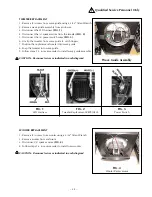
Страница 33: ...e replacement tweeter into wave guide 8 Snap the tweeter into wave guide 9 Follow steps 1 5 in reverse order to install wave guide assembly CAUTION Reconnect wires as indicated in each diagram Wave Gu...

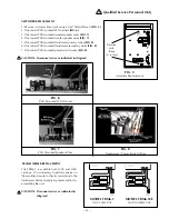
Страница 34: ...connect PCB mounted power switch wires FIG 8 CAUTION Reconnect wires as indicated in diagram FIG 5 Amplifier Replacement Remove only these 2 screws FIG 6 PCB Mounted LED Harness FIG 7 PCB Mounted Spea...

Страница 35: ...than Hafler or an Authorized Hafler service center 3 Any product purchased outside the United States please contact your local dealer 4 Shipping charges to get the unit to Hafler 5 Any product which...

Страница 36: ...This product is designed developed and assembled in the USA by a dedicated group of American workers The majority of the components used in the con struction of this product are produced by American...

Отзывы: