


16
RECOMMENDATION:
We recommend you to install the
metal box containing the electronic components at a distance
of at least 10 cm from the ground and sufficiently from all the
sources of heat (e.g.: side of an oven or hob).
If the instructions for installation for the gas hob specify a
greater distance, this must be adhered to.
Electrical connection
The hood must be connected to the mains supply by qualified
and trained technicians.
The mains power supply must correspond to the rating
indicated on the plate situated inside the hood. If provided with
a plug connect the hood to a socket in compliance with current
regulations and positioned in an accessible area, after
installation. If it not fitted with a plug (direct mains connection)
or if the plug is not located in an accessible area, after
installation, apply a double pole switch in accordance with
standards which assures the complete disconnection of the
mains under conditions relating to over-current category III, in
accordance with installation instructions.
Warning!
Before re-connecting the hood circuit to the mains
supply and checking the efficient function, always check that
the mains cable is correctly assembled.
Note:
in applications with a remote GME motor, connect the
cable of the motor unit in the designated terminal board
located inside the plastic box in the downdraft's wiring. Make
sure you follow the colours of the cables during the
connection.
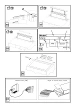
Fig. 21
Caution! Do not cut the cable between the hood and the
engine to avoid losing your right to warranty!
Mounting
Before starting to mount the appliance, make sure that no
component is damaged, otherwise contact the dealer and stop
mounting. In addition, read all the instructions below carefully.
•
Use an air outlet pipe no longer than 5 metres.
•
Limit the number of curves in the duct since each curve
reduces the suction effectiveness equivalent to 1 linear
metre. (E.g.: if two 90° curves are used, the duct should
be no longer than 3 metres).
•
Avoid drastic changes of direction.
•
Use a duct with 150mm diameter constant for the whole
length.
•
Use a duct made of standard complying material.
•
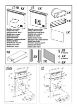
Remove the safety shim highlighted in the picture (
Fig. 1-
2
) at the end of the installation.
•
In case of failure to observe the instructions above, the
supplier can not be held responsible for capacity or noise
problems and no warranty will be granted.
•
Before making the hole, make sure that the inside of the
cabinet, near the hood housing area, does not have the
structure of the cabinet or other particulars which may
cause problems for the proper installation. Make sure
that the overall dimensions of the hood and the hob ae
compatible with the cabinet and therefore the installation
is feasible.
•
Perform, in the back of the hob, a rectangular hole with
the following dimensions:
(Fig. 20)
Hood 60cm Model:
542x100mm.
Hood 90cm Model:
842x100mm.
Hood 120cm Model:
1142x100mm
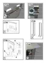
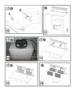
•
Install the hood in the hole made, inserting it from above,
as shown (
Fig. 3
). In case of version with motor on
board, it is necessary to remove the suction unit before
inserting the product into the cabinet.
•
Fix the hood inside the cainet using the special brackets
supplied (
Fig. 4
). Start mounting the brackets in the lower
part of the hood (
Fig. 5a
) making sure that there is a
distance of 2 mm between the lower part of the bracket
and the cabinet bottom (
Fig. 5b
). This distance allows
the traction of the product downwards on fixing, (
Fig. 5c
),
so that the stainless steel frame adheres perfectly on the
worktop.
•
Before inserting the screws into the cabinet, make sure
that the product is perfectly perpendicular to the worktop.
• After completing the installation and connecting the
product to the power supply, lift the hood and remove the
door lock (
Fig. 6
).
•
In case of version with motor on board start mounting the
motor unit directing the air outlet to the chosen position
downwards or upwards (
Fig. 7b
). The motor can be
installed on both the front side and the back one of the
hood. Once the installationof the motor has been
comleted, start mounting the duct for the air outlet.
•
In case of version with external motor put the suction unit
(external motor) in a suitable area and arrange the air
outlet duct. Start mounting the air outlet duct between the
external motor and the hood. Select the air outlet among
the five possibilities (
Fig. 7a
) and install the union
supplied.
•
Put the metal box containing the electronic components
in an easily accessible area for any assistance
operations (
Fig. 8
), connecting the electric connectors of
the same to the hood: pushbutton panel connector (
Fig.
9a
), 9-pole connector (
Fig. 9b
), neon connector (
Fig. 9c
)
•
In case of installation with remote motor,connect the
power unit cable to the special connector placed on the
electronic components box (
Fig.10a
)
•
Connect the product to the power supply