9
OPERATION MANUAL
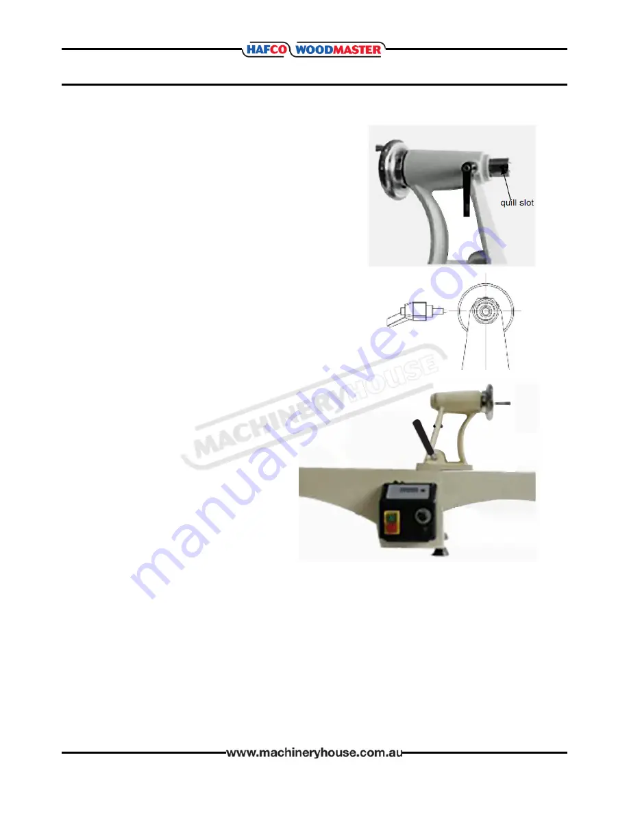
Installing The Lock Handle
3. Align the quill so that the slot is facing upward and
parallel with the top of the tailstock.
4. Install the locking handle into the top of the
tailstock so that it will enter into the slot of the quill.
Make sure the locking handle is in the correct
position by trying to rotate the quill. If it can not be
rotated, the locking handle and quill are in the
correct positions.
Adding a Bed Extension:
Each cast-iron Bed Extension adds 650mm)
to the lathe’s length.
1. Clean the joining ends of both the bed
sand the bed extension with a petro
leum base solvent.
Make sure there are no dents or burrs
on either of the mating surfaces.
Remove burrs and high spots with a
smooth file.
2. Place the two mating faces together
and install join area between beds with
the two M10 cap screws.
NOTE:
Only install finger tight at this time.
Warning!
Only use a soft face hammer to fit the Bed Extension. If the surfaces are damaged they will
affect the accuracy and tailstock action.
3. Move the tailstock until it is on top of the area where the Bed Extension face meets the
Lathe Bed face. The Bed Extension may need to be manipulated up, down or sideways in
order for the tailstock to fit.
4. With the Lathe Bed and Bed Extension in alignment, tighten the Tailstock Locking Handle
down in its current position.
5. Tighten the two M10 cap screws that were previously installed.
6. Check to ensure that the Tailstock moves freely over the mating joint and also over the
full length of the add-on Bed Extension. If there is a ridge between the two mating
surfaces, repeat steps1-5 again.
Page 10
Instructions Manual for WL-14V (W385)
11/08/2017


