Haes Haescomm HC228-S Скачать руководство пользователя страница 7


Page 7 of 21


The HC-228S Master Station weighs 6kg with batteries, so care should be taken to securely mount the 
Station on stud walling. 
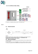
5.1


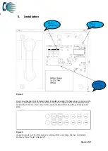
Connecting the HC-228S Master Station 

To comply with EMC (Electro Magnetic Compatibility) regulations and to reduce the risk of electrical 

interference in the system wiring, the use of fire-resistant screened cables is recommended throughout 
the installation. 

All wiring should come into the enclosure via the knockouts provided and be fixed tidily to the relevant 
terminals.  

Note that correct cable glanding is essential.  Due regard should be paid to any system specifications 
which demand a certain cable type, providing it meets the appropriate national wiring regulations.


5.2


Planning the Wiring 

All system wiring should be installed to meet the appropriate parts of BS5839 Part9:2021 and BS 7671 
(Wiring Regulations).  Other national standards of installation should be adhered to where applicable. 


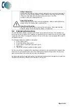
Do not test wiring using an insulation tester (Megger) with any 

equipment connected, as the 500 Volt test voltage will destroy 

these devices. 


You must observe local wiring regulations.  Do not run SELV and LV cables in the same enclosure 
without adequate insulation between them. 

5.3


Cable and Wiring Guidance 

5.3.1


Fire Telephone system 

Any system for use as a fire telephone system should use Type A outstations and must use enhanced 

grade cabling throughout for all wiring, including the mains supply to the HC-228S Master Station. 

5.3.2


Disabled Refuge EVC System 

For buildings less than 30m in height, or any building with sprinklers fitted, standard grade fire resistant 
cable may be used to wire Type B outstation and the mains supply to the Master Controller if the 

planned evacuation will be completed in 30 minutes.  
If the building is over 30m in height without sprinklers, or where the evacuation will take place over 

multiple stages exceeding 30 minutes, then enhanced grade cables must be used.  

5.3.3


Combined Systems 

Cabling to Type A or Type C outstations must be in enhanced grade fire resistant cabling.   

Individual spurs to Type B outstations can be wired in standard grade fire resistant cabling in 
accordance with the wiring guidelines already set out for disabled refuge systems. 

5.3.4


“Assist Call” Emergency Assistance Alarm Systems


All installations must conform to Building Regulations Approved Document M.  The “Assist Call” is wired 

using 2 core cable, and the “Assist Call” plates can be wired in any order.


5.3.5


Cabling methods 

There are 3 cabling methods available: 


Connection to a Type A or Type C outstation: use 2 core enhanced grade fire resistant cable 
when extending a firefighting telephone system. 


Connection to a Type B outstation: use 2 core standard grade fire resistant cable when 
extending a disabled refuge system. 


Connection to an “Assist Call” system on a dedicated line requires 2 core 1mm CSA or above 

PVC sheathed. 


Содержание Haescomm HC228-S

Страница 1: ...Page 1 of 21 Haescomm HC228 S EVCS Master Station Installation and Commissioning Manual Version 1 May 2022...

Страница 2: ...5 9 Powering down procedure 11 6 Set up procedure 11 6 1 HC 228S Master Station Display PCB Dipswitch Settings 12 6 2 Adding a Line Card 13 6 3 Removing a Line card 13 7 System Menus 13 7 1 Login Proc...

Страница 3: ...ty Fire telephone systems are recommended for all public buildings and multi story buildings over four floors that require phased evacuation as per BS 9999 2017 Disabled Refuge systems are required in...

Страница 4: ...UNIT MUST BE EARTHED Warning NO USER SERVICEABLE PARTS Each HC 228S Master Station requires local isolation with verification as per the Electricity at Work Regulations 1989 returning to a B6A breaker...

Страница 5: ...Use the 2 5mm AF Hex Key supplied to open the right hand front cover Verify the following items are present Correct number of Line Card depending on configuration c w 2 way line connectors 1 number 3...

Страница 6: ...are 14 knockouts on the top and 2 slotted entries with a dedicated mains supply entry at the rear If a knockout is removed by mistake fill the hole with a good quality cable gland Figure 3 Unused knoc...

Страница 7: ...stations and must use enhanced grade cabling throughout for all wiring including the mains supply to the HC 228S Master Station 5 3 2 Disabled Refuge EVC System For buildings less than 30m in height o...

Страница 8: ...at Work Regulations 1989 returning to a B6A breaker clearly marked EMERGENCY VOICE COMMUNICATION SYSTEM DO NOT TURN OFF 5 5 Battery Information In the event of mains failure BS 5839 9 2021requires bat...

Страница 9: ...ne number Dual line card One outstation per line output can be connected If no outstation is connected to the line output then an end of line 10k resistor should be fitted The dipswitch located on the...

Страница 10: ...ock in the controller and the earth stud in the Type A outstation 5 6 2 Type B outstation Figure 7 Note The Earth screen should be sleeved and connected to the terminal block in the controller and the...

Страница 11: ...Call emergency assistance alarm systems continuing to operate Calls from Type B outstations automatically time out after approximately 30 minutes It is advised that this feature is not used as the sys...

Страница 12: ...Line 1 2 Line 3 4 Line 5 6 Line 7 8 NA NA NA Reserved Remarks NA NA NA Line card 1 fitted NA NA NA Line card 1 2 fitted NA NA NA Line card 1 2 3 fitted NA NA NA Line card 1 2 3 4 fitted Figure 11 Dips...

Страница 13: ...ard 1 Remove all line terminals from the Line Card that is to be removed 2 Remove the securing screw 3 Remove the Line Card from Exchange PCB 4 Set the dipswitch on the Display PCB see 6 1 to disable...

Страница 14: ...delay period the relay will not operate and the timer will cease The above function works identically with the Assist Call emergency assistance system Enter the access level 3 code 1812 then press but...

Страница 15: ...t back to requesting a call and the zone LED will flash red to indicate this The call MUST be ended at the outstation 8 4 Putting a call on hold To put a call on hold press the zone button to select o...

Страница 16: ...ound on each new fault 8 8 Panel Indicator Test To test the panel indicators enter either the access level 2 code 1664 or access level 3 code 1812 menu then press zone button 2 All LEDs will illuminat...

Страница 17: ...logged in Magenta Engineer logged in Flashing green Call connected Flashing Red Green Call on hold Solid Yellow Master handset short circuit Figure 16 9 4 Zone indicator summary Zone Indicator Status...

Страница 18: ...be performed when the system is complete and the building has normal background noise levels The intelligibility test requires two personnel One person should be present at the master station the oth...

Страница 19: ...ntre above the display PCB the outstation zone template can be inserted here The template is in Word format and can be downloaded at www haes tech com Go to downloads section This can be completed pri...

Страница 20: ...Page 20 of 21 Notes...

Страница 21: ...re radial 1mm or 1 5mm Distance 500m from master station OUTPUTS Number 2 Fault In use Fault Relay 1 Volt free NC Com 30V DC 1A In Use Relay 1 Volt free NO Com 30V DC 1A CONTROLS AND INDICATIONS Butto...

Отзывы: