


Page 13 of 21
Figure 13
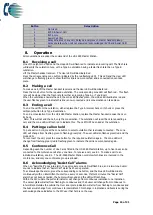
6.2
Adding a Line Card
The HC-228S Master Station is supplied with at least
one number
Line Card. There are 2 lines per
Line Card.
Before adding a Line Card, ensure that the HC-228S Master Station is not powered. If the HC-228S
Master Station is powered, then power down the HC-228S Master Station (see 5.9).
To fit the Line Card:
1.
Place Line Card in the next available space on the Exchange PCB and secure using
the supplied screw.
2.
Remove the line terminal and connect the field wiring.
3.
Push the terminal into the correct position on the Line Card.
4.
Set the dipswitch on the Display PCB (see 6.1) to enable Line Card monitoring.
Once the Line Card is securely fitted, power up the HC-228S Master Station (see 5.8).
6.3
Removing a Line card
Before removing a Line Card, ensure that the HC-228S Master Station is not powered. If the HC-228S
Master Station is powered, then power down the HC-228S Master Station (see 5.9).
To remove the Line Card:
1.
Remove all line terminals from the Line Card that is to be removed.
2.
Remove the securing screw.
3.
Remove the Line Card from Exchange PCB.
4.
Set the dipswitch on the Display PCB (see 6.1) to disable Line Card monitoring.
Once the Line Card has been removed, the HC-228S Master Station may be powered (see 5.8).
7.
System Menus
7.1
Login Procedure
For access level 2 (User) the code is 1664, for access level 3 (Engineer) the code is 1812. Enter the
relevant code using the numbered buttons 1-8, as each button is pressed the user LED will flash
cyan/magenta faster until the required code is entered, at which point LEDs 1-3 will illuminate cyan for
User mode and LEDs 1-5 will illuminate magenta for Engineer mode.
7.2
Fault Accept
Before accepting faults, the fault must be noted in the logbook, along with the time the fault was
reported.
To accept the fault, enter either the access level 2 (code: 1664) or access level 3 (code: 1812) menu,
then press zone button 1. The buzzer will silence, and the general fault LED will now go steady.
Press zone button 8 to exit this menu and to return to the menu options.
The buzzer will resound on each new fault and after 8 hours.
Содержание Haescomm HC228-S
Страница 20: ...Page 20 of 21 Notes...