


5.52.131.00.01.09
11
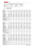
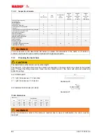
Table 2 (continuance 2)
Capacity
kg
40000
40000 50000 60000
Hoisting unit
AK9
AK9
*)
*)
Number of chain falls
2x4
2x4
FEM /ISO 4301
2m/M5
2m/M5
Load chain
mm
beam flange width
Load bar size 1N
Load bar size 2N
mm
mm
220-310
----
220-310
----
Lifting speed approx.
m/min
1,35/0,35
2/0,5
Hoist motor output
kW
2x5,5/1,4
2x8,5/2
Operating mode S3 % ED
40/25
40/25
Travel speed approx.
m/min
16/4
16/4
Travel motor output
kW
2x1/0,25
2x1/0,25
Operating mode S3 % ED
40/40
40/40
Travel path when reeling off 30 m of
hand chain
m
4 4
Hand chain pull of travel approx.
N
2x170
2x170
Noise emission at 1m distance
tolerance +2 dB(A)
dB (A)
75
75
max. wheel load approx. At 3m
suspension height
kg
5315
5315
Weight at 3m track height approx.
kg
2500
2520
3-phase current motor 400V/50Hz - IP55 – F – max. 1000 m above sea level.
Order-related Special data, refer to the motor nameplate.
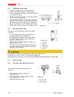
6 Installation
The assembly and installation depends on the local environment. The hoist must be suspended in a way that
it can position itself freely.
6.1 Trolley
For assembly on a beam a travel limit must be placed at either end of the track.
This must be attached so that any elastic limitation buffer or the trolley wheels are driven against them in
their end position when moving.
Generally, additional lifting gear (e.g. fork lift, lifting platforms) will be required for the assembly. These must
take the weight of the devices securely.
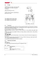
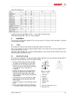
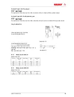
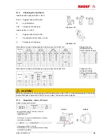
6.2
Adjusting the gauge
The trolley can be adjusted to various beam flange widths. Adjustment to the relevant beam flange width “B”
depends on the type and size and is to be made as follows:
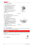
There are distance tubes (5) and/or washers
(6) situated on the load bars (2) of the trolley.
Dimension "X" is set by placing washers (6)
from the outer to the inner side ("X" increases)
or from the inner to the outer side ("X"
decreases).
Washers (6) and rubber discs (depended on
type) leave a distance for the load hook. It is
important that the load hangs in the middle
under the beam so that the two side plates are
equally loaded.
The suspension eye (9) (if existent) for bigger
load bolts must still be swivelling after it has
been secured.
Tighten the hexagon nut (3) and safety nuts (4)
again.
Check correct flange width "B" and dimension
"X". Adjustment must be repeated if necessary.
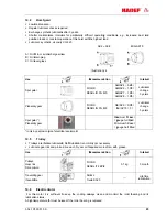
1 side
plates
2 load
bars
3 hexagon
nut
4 safety
nuts
5 distance
tubes
6 washers
7 ---
8 rubber disc (depended on type)
9 suspension eye