


Page 24
Explanations of Program Messages
8544operations.fm
Section 4
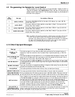
4.5 Explanations of Program Messages
Item
Number
Message
Description of Message
1
READY TO START
Indicates that a program is ready to start. To start, press
START PROGRAM
.
2
PROGRAM HALTED
Indicates the sampling program has been interrupted.
3
PROGRAM RUNNING
Indicates that a program is in process. Keys
0
,
1
and
2
are the only active keys while a
program is running. If running, halt the program (press
HALT PROGRAM
) before entering
a new program.
4
PROGRAM COMPLETE
This message is displayed after program completion. To repeat the program, press
START PROGRAM
. Press
NEW PROGRAM
to enter a different program.
5
RE-ENTER PROGRAM,
DEPRESS *
When the sampler is on, this message will appear if the sampler was turned off during
program entry.
6
PROGRAM DELAY
This is the first message in the programming sequence. If selected, the sampler will
start only after the delay period elapses. A
YES
response causes message 6a to appear
on the display.
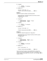
6a
10:35 AM 21JUL03
A time and date are displayed when
YES
is pressed in response to message 6. The
example to the left signifies 10:35 in the morning, on October 24, 2000.
7
TIMED MODE
If selected, the sampler will operate on a timed cycle basis. Press
YES
to prompt the
user to enter the number of minutes desired for the time interval between samples.
Press
NO
to prompt the question described in item 8.
7a
INTV = _ _ _ _MIN
Enter the value for the interval between samples (in minutes).
8
FLOW MODE?
Press
YES,
the cause the sampler to operate on a flow proportional basis. It will prompt
the you to enter the number of flow signals that you want the sampler to count down
between samples. Press
NO
to prompt the question in item 7.
8a
INTV = _ _ _ _CNTS
Enter the value for the number of pulses (counts) that you want to accumulate between
samples. To determine the appropriate number, refer to the programming instructions
for flow proportional operation in
section 4.11
.
9
OTHER CHANGES
Press
NO
to retain the previously entered program entries for all remaining programming
steps, and return to the "Ready to Start" standby state. Press
YES
to change the
previously programmed entries for all items 10 through 16.
10
COMPOSITE MODE,
CONTINUOUS MODE
This message appears if only one bottle is entered for the total number of bottles in the
parameter entry mode. Press
YES
to the "Continuous Mode?" prompt to take samples at
the programmed interval. The program will terminate only with a full bottle when using
the full bottle float switch (Cat. No. 8847). Press
NO
to cause the display to read
"samples = _ _ _". This permits you to enter the desired number of samples, after which
the program will terminate.
11
CHANGE VOLUME?
Press
NO
to retain the sample volume from the previous program (programming items
13, a–h are skipped), and the display will prompt the message in item 14.
12
SAMPLE VOL = _ _ _
Enter the desired sample volume (in mL) to be delivered to the sample container each
time a sample is initiated.
13
CALIBRATE VOL?
This message appears after you enter sample volume. If greater volume accuracy is
desired, press
YES
. Press
NO
to skip the calibration and go to the next step.
13a
READY TO PUMP?
When
YES
is pressed the sampler will pump to collect one sample. The pump will first
pre-purge the intake line, draw sample liquid, and then post-purge.
Before pressing
YES
, pull the pump tubing off of the fitting where it enters the sampler
housing and place a graduated cylinder at the sample discharge point.
13b
STOP AT MARK
After pressing
YES
in response to item 13a, the pump will pre-purge the intake line and
begin pumping liquid into the graduated container. When the desired volume has been
delivered, press
STOP PUMP
. The pump will then purge the intake tubing. The sampler
will hold the time to deliver the desired sample volume in memory. This timed volume is
repeated for subsequent samples.
Содержание SIGMA 900
Страница 2: ...Visit http www hach com...
Страница 6: ...Visit http www hach com...
Страница 20: ...Visit http www hach com...
Страница 32: ...Visit http www hach com...
Страница 40: ...Visit us at www hach com...
Страница 42: ...Visit http www hach com...
Страница 44: ...Visit http www hach com...


