background image

3.3 Accessories installation

3.3.1 External pressure sensor

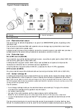
The system can be fitted with an external pressure sensor. This enables a measurement of fraction
of gas under variable pressure conditions during gas phase measurement.

Note: Do NOT exceed the pressure range of the sensor. This would permanently deform the sensor membrane,
thus delivering incorrect pressure values in the future.

The external sensor connects to the ORBISPHERE measuring equipment with a 1 meter cable and a
4 pin connector (an optional extension cable can be used, but total length should not exceed 50 m.).
The external pressure sensor can be installed in the 32002.xxx multi parameter flow chamber. It is
held in place by a blue threaded collar. Tightness is assured by the O-ring on the sensor seat.
Two models are available, depending on application. Refer to 

Figure 5

.

• 28117—Pressure sensor 0 to 5 bar absolute
• 28117C—Pressure sensor 0 to 1 bar absolute

Figure 5  External pressure sensor

3.3.2 Weld-on stainless steel socket

The 29501 weld-on sensor socket can be used to install a sensor into a stainless steel pipe (min.Ø
50 mm or 2”). When welding the socket to the pipe, check that setback between the pipe’s inner
diameter and the sensor tip does not exceed 4 mm. Refer to 

Figure 6

.

Note: Be sure to remove the two O-rings from the socket before welding and leave the sensor’s stainless steel cap
screwed on during welding to prevent thread distortion.

Recommendation: To facilitate sensor removal and installation, we suggest installing the socket in a
location where the liquid can be drained quickly and easily. By creating a one meter long piece of
pipe (shown below) with shut off valves at both ends, just a small volume of liquid needs to be
drained to enable sensor removal. Also, a precise sensor and socket installation can be performed in
the workshop, and this assembly can be placed in the production line with minimal down time. Refer
to 

Figure 7

.

English


15

Содержание GA2 00 Series

Страница 1: ...DOC344 52 93153 ORBISPHERE Model GA2X00 O2 EC Sensor 11 2019 Edition 2 User Manual...

Страница 2: ......

Страница 3: ...Installation 10 3 1 Sensor preparation 10 3 2 Sensor installation 13 3 2 1 Sensor positioning information 13 3 2 2 Sensor insertion 14 3 2 3 Sensor removal 14 3 3 Accessories installation 15 3 3 1 Ext...

Страница 4: ...Table of Contents 2...

Страница 5: ...erials Stainless steel Stainless steel or hastelloy Sensor head Kalrez O rings Sensor bottom Viton O rings1 EPDM and Kalrez O rings Sensor head Kalrez O rings Sensor bottom Viton O rings or Kalrez O r...

Страница 6: ...GA2400 S00 2956A A 33051 S0 Dissolved oxygen traces with 3655 Portable GA2400 S00 2956A A 33051 S0 Table 4 ATEX Sensor Membrane Cartridge Protection Cap GA2800 SVS 2956A A or 29552A A 33051 SG GA2800...

Страница 7: ...sec 200 100 30 30 Recommended gaseous flow rate L min 0 1 to 3 1 3 2 Oxygen sensors Table 2 Table 6 Membrane specifications Oxygen sensors 2 Specification 2935A A 29521A A 2995A A Recommended applica...

Страница 8: ...product including without limitation direct incidental and consequential damages and disclaims such damages to the full extent permitted under applicable law The user is solely responsible to identify...

Страница 9: ...anode immersed in an electrolyte solution which is separated from the gaseous or liquid sample by a gas permeable membrane An electronic circuit is linked to the anode and cathode Through an applied...

Страница 10: ...Sensor body 7 Cartridge containing electrolyte and membrane 3 Sensor collar 8 Cotton washer 4 Plastic base 9 Silicone disc 5 Protection cap locking washer 2 3 Product components Make sure that all co...

Страница 11: ...l be delivered with each sensor part number 33051 SG or 33051 H0 2 3 3 Sensor recharge kit A recharge kit should have been ordered with the sensor as this will be required to initially make the sensor...

Страница 12: ...emicals that are handled Refer to the current safety data sheets MSDS SDS for safety protocols Your sensor has been thoroughly cleaned and tested at the factory before shipment It has been shipped wit...

Страница 13: ...it on top of the anode Take a new cotton washer from the recharge kit Hold it between thumb and forefinger and position it on top of the silicone disc Note During this step it is very important to ens...

Страница 14: ...nger dry 8 Gently screw the sensor clockwise into the replacement cartridge applying minimum pressure to avoid any damage to the screw threads 9 Continue turning until the cartridge is attached to the...

Страница 15: ...urn it clockwise to avoid unscrewing the cartridge 13 Finally screw the protection cap locking washer back into place in a clockwise motion and tighten finger tight 3 2 Sensor installation 3 2 1 Senso...

Страница 16: ...rings if product leaks are visible Refer to Figure 4 for sensor installation into a micro volume flow chamber Note Do not twist the sensor when inserting it into a micro volume flow chamber This rota...

Страница 17: ...o 5 bar absolute 28117C Pressure sensor 0 to 1 bar absolute Figure 5 External pressure sensor 3 3 2 Weld on stainless steel socket The 29501 weld on sensor socket can be used to install a sensor into...

Страница 18: ...nd a pressure of up to 20 bars with the sensor in place or not Refer to Figure 8 Sensor insertion is made by inserting the sensor into the housing and tightening the retaining collar until it stops As...

Страница 19: ...housing and tightening the retaining collar until it stops Removal is made by unscrewing the collar and pulling the sensor out Be sure that the sample flow has been turned off before inserting or remo...

Страница 20: ...7 in add 100 mm 3 94 in for connection length Table 7 Flow Chamber Orientation Sample Orientation of flow chamber Gaseous or liquid media Vertically with connections down and sensor up Center connecti...

Страница 21: ...ss steel plugs provided model 28123 The flow chamber is connected to 6 mm or stainless steel tubing by two Swagelok fittings If necessary copper or plastic tubing with a very low permeability can be s...

Страница 22: ...Shown here with gas sensor right pressure sensor center optional second sensor left Section 4 Maintenance W A R N I N G Multiple hazards Only qualified personnel must conduct the tasks described in t...

Страница 23: ...r part no 29331 and cloth part no 2934 32301 Electrochemical cleaning and regeneration center see below 40089 Tweezers for maintenance kits DG33303 Cleaning tool for sensor polishing for A110X and C11...

Страница 24: ...e then remove the Dacron mesh from inside the cap and discard it 3 Hold the sensor with the membrane facing down to avoid spilling any electrolyte then carefully unscrew the old cartridge Drain the ol...

Страница 25: ...filled with water 8 On the clean polishing cloth 2934 do the steps that follow a Add a few drops of water b Spread a little of the polishing powder 29331 to form a grey milky liquid 9 Screw the polis...

Страница 26: ...tool over the sensor head Pour enough electrolyte 2959 into the cleaning tool until it completely covers all the electrodes Note For DG33619 regeneration cell screw the regeneration cell on the senso...

Страница 27: ...repeat the cleaning process if necessary 18 When cleaning is complete unplug the sensor from the cleaning center and re install the plastic sensor base for the rest of the procedure Remove any remain...

Страница 28: ...any visible bubbles in the electrolyte remove them using a stirring motion with the packing component Note The recharge cartridge container will be colored black for all applications except for the 61...

Страница 29: ...e center of the protection cap It is very important that the mesh is in the center of the protection cap and covering the entire grille Lower the sensor onto the protection cap making sure not to dist...

Страница 30: ...ed sensor operation in relatively high dissolved O2 concentration High O2 concentrations generate deposits more quickly Install a less permeable membrane Turn off the analyzer when sensor is not in a...

Страница 31: ...ersonal injury damage to the instrument or equipment malfunction The replacement parts in this section are approved by the manufacturer Note Product and Article numbers may vary for some selling regio...

Страница 32: ...Flow chamber in stainless steel 316 for use with for model 28117 and 28117 C pressure sensors 32006 Flow chamber in Delrin for the 3655 portable instrument with one meter of tubing 32007D Flow chamber...

Страница 33: ...des o rings cotton washers and cleaning tools 29521A A Recharge kit of 4 pre filled cartridges with premounted 2952A membranes for A1xxx and GA2x00 oxygen sensors Includes o rings cotton washers and c...

Страница 34: ...78 x 1 78mm 5 pieces 28093 0 Kalrez O ring for pressure sensor 28117 X 18 78 x 1 78mm 1 piece 28093 2 Nitril O rings for pressure sensor 28117 X 18 78 x 1 78mm 5 pieces 28093 4 EPDM O ring set for sta...

Страница 35: ......

Страница 36: ...0 669 2932 orders hach com www hach com HACH LANGE GMBH Willst tterstra e 11 D 40549 D sseldorf Germany Tel 49 0 2 11 52 88 320 Fax 49 0 2 11 52 88 210 info de hach com www de hach com HACH LANGE S rl...

Отзывы: