


12.3. Maintaining the primary air limiter
The primary air limiter (PAL) is inserted at the back or
the side of the inner stove (see Figures 1, 2 and 19). A
pendulum flap is located inside the automatically
operating PAL. The PAL serves for the economical
heating of your stove. To make the PAL accessible, the
rear wall (“Viking”) or the inspection panel (“Ibiza”) of
your oil stove must be removed. Lightly compress the
housing with the hand so that the PAL can be pulled
out from the preheating chamber (see Figures 1 + 2).
Remove any dust that may be present using a vacuum
cleaner. To install, simply insert the PAL snugly in the
existing opening in the burner jacket (important: Large
round section must be at the bottom, see Figure 19).
Following this, ensure the unobstructed movement of
the pendulum flap by tapping on it carefully. The flap
could be jammed due to vibrations during the transport
of the stove or suchlike. Such a condition must be
rectified.
12.4. Cleaning the appliance surfaces
The view window pane and the painted surfaces of the
appliance are best cleaned with warm water and soap
or other commercially available cleaning agents. Do not
use any abrasive cleaning agents as this would
damage the glass and also the metal surfaces by
scratching. Clean the painted parts only with the stove
in cold condition to prevent the formation of cracks or
stains.
12.5. Maintaining the electric ignition
As already mentioned at the beginning of this
chapter, always pull the power plug whenever
working on the appliance!
Work on the electric units of the appliance must only be
carried out by the works service or trained technical
personnel except for the following.
Replacing the ignition bar:
The ignition bar can be easily replaced on the oil stove
with electric ignition. A defect on the ignition bar can be
identified in that the ignition coil
fails to glow
with cold
stove and ignition switched on. This can be verified
through the opened fire chamber door.
1. Disconnect inspection panel.
2. Disconnect the two cables (supply line) from the
ignition bar (Figure 17).
3. Loosen the two mounting screws of the retaining
plate (see figure 24) and remove the retaining plate
with a short anti-clockwise movement.
4. Pull the ignition bar from the burner by lightly
turning 90°.
5. It is imperative to secure the glass fibre seal
(approximately 2
– 3 mm diameter, see Figure 24),
around the new ignition bar, to completely seal the
hole.
6. Place the tension spring on the ignition bar.
7. Install the ignition bar in reverse order (4. to 1.).
Please note that the cables on the connection
terminals of the ignition bar are screwed on tightly
to ensure sound electrical contact.
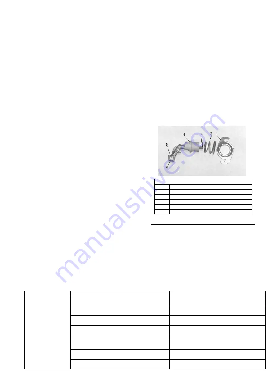
Figure 24:
Ignition bar components
1
Retaining plate
2
Compression spring
3
Connection terminals
4
Glass fibre seal
5
Ignition coil
6
Evaporator coil
Replacing the microfuse in the ignition transformer:
Disconnect the inspection panel. The microfuse is
integrated in the ignition transformer. To replace it,
merely insert a screwdriver in the screw cap and
remove the cap (see Figure 16). The fuse has the
following rating:
M 500 mA, 250 V.
13.
Problem solutions
– what to do if... ?
In the following table we have listed some problems, their cause and proposed remedies. Because of the wide range of
possible fault causes the list cannot be complete. If you cannot rectify the malfunction of the appliance with this list,
consult your specialist dealer.
Problem
Reason
Solution
-
Insufficient
oil
stove draught
-
Flue gas escapes
upon igniting or
shortly thereafter
and/or during the
heating phase
-
Soot deposits in
the oil stove
Chimney or flue gas pipe are leaking
Clarify with chimney-sweeper, on flue pipes,
check tight joints and reseal if required
The flue pipe connection between oil stove and
chimney is unfavourable.
See Chapter 9. “Connection to the chimney”
Chimney incorrectly dimensioned.
Clarify with chimney-sweeper: possibly increase
chimney or fit chimney attachment.
A door of other fireplaces connected to the
chimney is open.
Close the doors of other fireplaces.
Chimney cleaning openings are open.
Close these cleaning openings.
Appliance, flue pipes or chimney are sooted-up or
clogged.
See Chapter 12. “Cleaning and maintenance”.
Slag in the area of the burner base
Clean burner, especially pierce open the air
holes in the burner wall (see Chapter 12.1.)
Insufficient fresh air supply.
See Chapter 2. “General information, safety
instructions”.


