background image

Cleaning

work

GB

3

3. Cleaning work

WARNING

Before starting any cleaning work, the stove must be cool down!
Once the cleaning work is completed, the correct operating status of the device must be re-
established: Put the combustion pot in correctly, close the combustion chamber door.

3.1. Cleaning the surface

Dirt on the upper surface of the stove may be cleaned off with a damp cloth or if necessary with mild soapy
water. You are advised against using corrosive cleaning agents and solvents since these might damage the
surfaces.

3.2. Cleaning the glass panel

To clean the viewing panel, you must first open the stove door. Dirt on the glass panel can be removed with a
glass cleaner or with a damp sponge on which you have sprinkled some of the wood ash present.
(Environmentally friendly). Cleaning the glass panel may only be done with a cooled down stove in the OFF
operating mode.

3.3. Clean combustion chamber “function instruction” Error
F040

• The whole combustion space must be cleaned after

30-hours operation at the latest, or once a week

.

• The requirement to clean the fire-box (flickering of the display) appears during heating, in case that the

cleaning interval has elapsed.

• After the fire-box has been cleaned, the error message "Clean the fire-box" will be confirmed automatically.

The condition for automatic confirmation of this error message is that the fire-box door is opened for more
than

60 seconds

. This time is necessary for careful cleaning of the fore-box, including the burner.

• This reset of the operating hours counter occurs even if the cleaning of the combustion chamber is

performed before the 30 operating hours have run provided that the stove is in “Off” operating status and the
door is open for longer than 60 seconds during cleaning.

3.4. Cleaning the combustion pot - weekly

During operation, deposits may form in the combustion pot. How quickly the combustion pot becomes dirty
depends solely on fuel quality. The deposits or encrustations must be removed from time to time.

Содержание 0553508020000

Страница 1: ...HSP 6 Pallazza III 535 08 PGI Equipment sheet Pellet stove GB 0553508021413a Equipment sheet HSP 6 Pallazza III 535 08 PGI ...

Страница 2: ...the heating device or of an injury The note entitled Notice advises you on possible damage to your heating device The note entitled Important calls your attention to the information important for the operation of your heating device The note itself calls your attention to the information important for the operation of your heating device in general ...

Страница 3: ...n instruction Error F040 3 3 4 Cleaning the combustion pot weekly 3 4 Maintenance work 5 4 1 Cleaning the flue gas passes 5 4 2 Cleaning the pellet container annual maintenance 8 5 Replacement parts list 9 5 1 Replacement parts list Pallazza III 535 08 PGI without trim parts 9 5 2 Detail A1 11 5 3 Replacement parts list Pallazza III 535 08 PGI 12 6 Circuit diagram 13 ...

Страница 4: ......

Страница 5: ...tents of storage container pellet tank about 32 kg Duration of burn with one charge min max about 20 h 60 h Permitted fuel Low dust wood pellets Diameter 6 mm to Ö Norm M 7135 DIN plus EN plus A1 Length max 30 mm Room heating capacity to Ö Norm M 7521 max 230 m Room heating capacity to DIN 18893 constant heating 250m 145m 98m Room heating capacity to DIN 18893 timed heating 165m 95m 65m Electricit...

Страница 6: ...Dimensions GB 2 2 Dimensions ...

Страница 7: ...ustion chamber function instruction Error F040 The whole combustion space must be cleaned after 30 hours operation at the latest or once a week The requirement to clean the fire box flickering of the display appears during heating in case that the cleaning interval has elapsed After the fire box has been cleaned the error message Clean the fire box will be confirmed automatically The condition for...

Страница 8: ...ering in the pellet tank might possibly result This will destroy your device and is not covered in your guarantee WARNING Cleaning the combustion pot may only be done with a cooled down stove in OFF operating mode Otherwise there is a risk of burns Take out the burner bowl from the stove Remove the remains of ashes and slag After the cleaning mount the burner bowl back to its proper position on th...

Страница 9: ...h content is higher 0 5 and over the interval from maintenance to maintenance is reduced and the accumulation of ash increases by 2 or 3 times WARNING Devices that are not maintained in accordance with our specifications must not be operated Failure to observe this point will invalidate all guarantee claims 4 1 Cleaning the flue gas passes CAUTION Check and clean the flue gas ways exhaust flue gas...

Страница 10: ...Maintenance work GB 6 Figure 1 Removing the flue baffle ...

Страница 11: ...work GB 7 Figure 2 Removing the side wall CAUTION After completion of the cleaning make sure that when putting back the covers the seals are seated in the right positions It is essential to replace defective seals ...

Страница 12: ... 1 in the pellet tank may be removed Then clean the tank and the intake of the screw conveyor housing with a vacuum cleaner After cleaning it is essential to put back the protective grille When doing this make sure that no screws fall into the pellet tank so as to avoid consequential damage to the screw conveyor Figure 3 Pellet tank 1 Protective grille 2 Tank cover ...

Страница 13: ...Replacement parts list GB 9 5 Replacement parts list 5 1 Replacement parts list Pallazza III 535 08 PGI without trim parts ...

Страница 14: ...tery CR 2032 1 piece 13 Stand 4 piece 0551908505005 14a Ignition 1 piece 0541908005202 14b Lighter case 1 piece 0553808005215 15 Room temperature sensor 1 piece 0089500390005 16 Flue gas thermosensor 1 piece 0561008005540 17 OC 1 piece 0089500080005 18 Cover hinge pins DIN 427 M5x18 1 piece 0551908005015 19 Protective grille 1 piece 0551908005931 20 Closure frame 1 piece 0551908005160 21 Framework...

Страница 15: ...5 37 Screw UN5950 M5x10 4 piece 38 Air hose 1 piece 0551908015315 5 2 Detail A1 Pos Description Piece No PR Detail A1 A1 1 Screwing door Set 1 piece 0551908005001 A1 2 Door hinge Set 1 piece 0551908005002 A1 3 Glass holder Set 1 piece 0551908005003 39 Combustion chamber door black 1 piece 0551908007201 40 Seal glass 10x4 mm 900 mm 1 piece 0040210040005 ...

Страница 16: ... parts list Pallazza III 535 08 PGI 43 Side wall rear right 1 piece 0553408025500 44 Side part C ceramic white right 1 piece 0553208126185 45 Side wall front right 1 piece 0553408026300 46 Front plate anthracite 1 piece 0553408007200 47 Side wall rear left 1 piece 0553408025510 48 Side part C ceramic white left 1 piece 0553208126186 49 Side wall front left 1 piece 0553408026310 50 Back wall 1 piec...

Страница 17: ...Circuit diagram GB 13 6 Circuit diagram Circuit diagram IO 33 3 ...

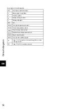
Страница 18: ...conveyor motor 7 Induced draught 8 9 OC 35 36 Flue gas temperature sensor 37 38 Flame temperature sensor 39 40 Room temperature sensor 41 42 Bottom flame temperature sensor 43 44 Door contact switch 48 50 Flue gas fan rotation speed F1 Fuse T 3 15 A ignition induced draught fan screw conveyor motor F3 Fuse T 0 315 A operator console ...

Страница 19: ......

Отзывы: