background image


2-18 

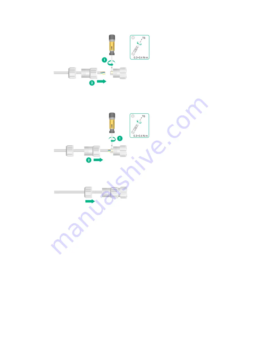
Figure2-34 Feeding a cable through the sealing nut 


3. 

Use a Phillips screwdriver to fasten the screws for the wires to be secured to the adapter 
header, and then fasten the sealing washer to the header. 

Figure2-35 Securing the power cord wires to the adapter header 


4. 

Use a wrench or wear nonslip gloves to fasten the sealing nut to the sealing washer. 

Figure2-36 Fastening the sealing nut 


5. 

Connect the power cord to the AP. Apply weatherproof tape over the connection and smooth 
the tape edges to ensure full adhesion. 

Содержание WA6628X

Страница 1: ...H3C WA6628X Access Point Installation Guide New H3C Technologies Co Ltd http www h3c com Document version 5W102 20210127 ...

Страница 2: ...respective owners Notice The information in this document is subject to change without notice All contents in this document including statements information and recommendations are believed to be accurate but they are presented without warranty of any kind express or implied H3C shall not be liable for technical or editorial errors or omissions contained herein Environmental protection This produc...

Страница 3: ...s that are optional x y Braces enclose a set of required syntax choices separated by vertical bars from which you select one x y Square brackets enclose a set of optional syntax choices separated by vertical bars from which you select one or none x y Asterisk marked braces enclose a set of required syntax choices separated by vertical bars from which you select a minimum of one x y Asterisk marked...

Страница 4: ...as a Layer 2 or Layer 3 switch or a router that supports Layer 2 forwarding and other Layer 2 features Represents an access controller a unified wired WLAN module or the access controller engine on a unified wired WLAN switch Represents an access point Represents a wireless terminator unit Represents a wireless terminator Represents a mesh access point Represents omnidirectional signals Represents...

Страница 5: ...Documentation feedback You can e mail your comments about product documentation to info h3c com We appreciate your comments ...

Страница 6: ...P 2 3 Mounting the AP in a PDC 2 3 Mounting the AP on a wall 2 5 Mounting the AP on a vertical pole 2 8 Mounting the AP on a horizontal pole 2 10 Adjusting the AP angle 2 11 Connecting cables 2 12 Connecting an Ethernet cable 2 12 Connecting a fiber cable 2 13 Connecting a feeder line 2 15 Connecting the power cord 2 16 Connecting the grounding cable 2 19 Labeling cables 2 20 Verifying the install...

Страница 7: ... to high temperature dust harmful gases electromagnetic interference sources high power radars radio stations or electrical substations unstable voltage heavy vibration and loud noise The location is not water seeping water soaking and condensing The location is away from inflammable and explosive substances The AP uses built in omnidirectional antennas For the optimal coverage make sure the insta...

Страница 8: ... AP onto the grounding conductor and use anti erosion treatment on the welding joint With a cross section area of a minimum of 6 mm 2 0 01 in 2 the grounding cable must be as short as possible and must not be coiled Make sure the grounding terminals of all the lightning arresters of the AP and the peer device of the AP are reliably grounded Ground lead A ground lead is a metal conductor connecting...

Страница 9: ...lation accessories Figure1 1 Installation accessories Installation tools When installing the AP you might need the following tools Prepare the installation tools yourself as required Figure1 2 Installation tools ...

Страница 10: ...ing design Arrange cables firmly and neatly without crossing twisting or cracking them Do not route cables together with high voltage electric power pipelines fire fighting pipes or lightning protection cables to avoid the electromagnetic interference Use PVC pipes iron pipes Plica tube or cable troughs for cable routing Route cable pipes and troughs neatly against the wall and connect them throug...

Страница 11: ...allation Power on the AP Operating correctly Power off the AP Troubleshoot the AP End Yes No Connect cables Ethernet cable fiber cable and feeder line Ground the AP Mount the AP in a PDC Yes No Attach the AP bracket Mount the AP on a wall Mount the AP on a horizontal pole Mount the AP on a vertical pole Optional Adjust the AP angle ...

Страница 12: ...l pole make sure the vertical pole mounting arrow on the AP bracket points up To mount the AP on a horizontal pole make sure the horizontal pole mounting arrow on the AP bracket points up To mount the AP on a wall you can orient the AP bracket horizontally or vertically as required Figure2 2 Attaching the AP bracket to the AP Mounting the AP in a PDC You can mount the AP in a power distribution ca...

Страница 13: ...ure2 4 Installation holes in the AP rear Attaching the AP brackets to the AP Attach the AP brackets to the AP Align the screw holes in the AP brackets with the installation holes at the AP sides and use M8 screws to attach the AP brackets to the AP Tighten the screw to a torque value of 12 4 Nm ...

Страница 14: ...AP on a wall with the horizontal pole mounting arrow on the AP bracket pointing up adjust the installation direction of the wall pole bracket accordingly To mount the AP on a wall 1 Use the wall pole bracket to mark four installation holes on the wall Figure2 6 Marking the installation holes 2 Use a hammer drill to drill holes with a diameter of 8 mm 0 32 in at the marked locations as shown in Fig...

Страница 15: ... rubber hammer until the expansion sleeve is flush with the wall surface as shown in Figure2 8 Figure2 8 Hammering an expansion bolt into a hole 4 Fasten the nut on each expansion bolt to expand the expansion sleeve Figure2 9 Fastening the nut on an expansion bolt 5 Remove the nut and washers from each bolt ...

Страница 16: ... wall and then fasten the nuts and washers on the expansion bolts to secure the wall pole bracket to the wall Figure2 11 Attaching the wall pole bracket to the wall 7 Orient the AP with the vertical pole mounting arrow on the AP bracket pointing up Use M5 20 screws to secure the AP bracket attached to the AP to the wall pole bracket ...

Страница 17: ...ertical pole The optional band clamps support poles with a diameter of 60 to 80 mm 2 36 to 3 15 in If the diameter of the pole is not in the range prepare band clamps yourself To mount the AP on a vertical pole 1 Use band clamps to secure the wall pole bracket to the vertical pole ...

Страница 18: ...t to the vertical pole 2 Orient the AP with the vertical pole mounting arrow on the AP bracket pointing up Use M5 20 screws to secure the AP bracket attached to the AP to the wall pole bracket Figure2 14 Attaching the AP to the wall pole bracket ...

Страница 19: ...orizontal pole Figure2 15 Securing the wall pole bracket to the horizontal pole 2 Orient the AP with the vertical pole mounting arrow on the AP bracket pointing up Use M5 20 screws to secure the AP bracket attached to the AP to the wall pole bracket Figure2 16 Attaching the AP to the wall pole bracket ...

Страница 20: ...cal pole mounting arrow on the AP bracket pointing up you can adjust the AP to the desired elevation angle the adjustment angle must not exceed 60 degrees If the AP is installed with the horizontal pole mounting arrow on the AP bracket pointing up you can adjust the AP to the desired azimuth angle the adjustment angle must not exceed 60 degrees Figure2 17 Adjusting the AP angle on a vertical pole ...

Страница 21: ...reases or wrinkles and press the tape against the connection so that there are no gaps Smooth each wrapped layer with your hands to ensure full adhesion To prevent device damage attach weatherproof caps tightly to connectors that are not in use Connecting an Ethernet cable Use Category 5e or above Ethernet cables only As a best practice use shielded twisted pair STP cables To connect an Ethernet c...

Страница 22: ...ector Connecting a fiber cable WARNING To avoid cable damage do not pull the fiber cable with excessive force To avoid affecting fiber performance make sure the fiber cable is not bended or folded when fastening the sealing nut IMPORTANT Before connecting a fiber cable remove the dust caps from the fiber connectors To use a fiber pigtail that does not have any protective sleeve first use weatherpr...

Страница 23: ... connector 4 Attach a transceiver module to the SFP connector and then connect the fiber cable to the transceiver module Figure2 26 Connecting a fiber cable 5 Adjust the weatherproof connector to ensure that the fiber is not bended or folded and then fasten the weatherproof connector Figure2 27 Fastening the weatherproof connector 6 Use a wrench or wear nonslip gloves to fasten the sealing nut Fig...

Страница 24: ...ring design requirements in the working frequency band You can connect an RF cable or antenna to an antenna connector The connection procedure is the same The following procedure connects an RF cable to an antenna connector To connect a feeder line 1 Remove the weatherproof plug from the antenna connector on the AP 2 Connect a lightning arrester to the antenna connector 3 Connect the feeder line t...

Страница 25: ... loads to unused antenna connectors Connecting the power cord WARNING If you install the AP at a humid location make sure the power source can provide good grounding fault protection When connecting the power cord first connect the power cord to the AP and then connect the power cord to the power source Use a weatherproof power cord ...

Страница 26: ...aps Smooth each wrapped layer with your hands to ensure full adhesion AC liquid tight adapter Figure2 32 shows a AC liquid tight adapter Table2 1 describes the adapter specifications Figure2 32 AP power connector and AC liquid tight adapter header Table2 1 Weatherproof AC connector specifications Item Specification Cable diameter 5 5 to 8 mm 0 22 to 0 32 in Maximum current 20 A Maximum voltage 250...

Страница 27: ... then fasten the sealing washer to the header Figure2 35 Securing the power cord wires to the adapter header 4 Use a wrench or wear nonslip gloves to fasten the sealing nut to the sealing washer Figure2 36 Fastening the sealing nut 5 Connect the power cord to the AP Apply weatherproof tape over the connection and smooth the tape edges to ensure full adhesion ...

Страница 28: ...ning protection and EMI protection Before connecting the AP to the power source make sure the grounding cable is correctly connected Feed the ring terminal end of the grounding cable through the base and then use the grounding screw to attach the ring terminal to grounding point on the AP Figure2 38 Connecting the grounding cable to the AP ...

Страница 29: ...IMPORTANT Make sure all cables are correctly connected and the AP is connected to the power source correctly before powering on the AP Switch on the external power source and verify that the AP is operating correctly by examining the LED on the AP For more information about the LED see Appendix B LEDs and Ports Connecting the AP to the network All AP settings are configured on the AC To verify net...

Страница 30: ...2 21 C Config DC DataCheck R Run M Master B Backup AP name APID State Model Serial ID ap1 1 R M WA6628X 219801A2ER8179E00001 ...

Страница 31: ...ecifications Table3 1 Technical specifications Item Specification Dimensions H W D 280 280 85 mm 11 02 11 02 3 35 in Weight 3 2 kg 7 05 lb System power consumption 52 W IEEE standards IEEE802 11a b g n ac ax Material Cast aluminum ...

Страница 32: ...AP has registered with an AC but does not have any associated clients Flashing at 0 5 Hz The AP is starting up Flashing at 1 Hz Only the 2 4G radio has associated clients Flashing at 2 Hz The AP is upgrading the image Blue Flashing at 1 Hz Only the 5G radio has associated clients Alternating between green and blue at 1 Hz Both the 2 4G and 5G radios have associated clients Ports Figure4 1 Front vi...

Страница 33: ...4 2 Figure4 2 Left view 1 to 4 Antenna ports ANT1 2 3 4 for radio 1 5G or radio 2 2G Figure4 3 Right view 1 to 4 Antenna ports ANT5 6 7 8 for radio 1 5G Figure4 4 Rear view 1 Vent valve ...

Страница 34: ...nd Ten Gigabitethernet 1 for configuration on the AC 10GE2SFP IEEE802 3 SFP MSA SFF 8427 Connects the AP to an uplink device for Internet or MAN access It is represented by interface XGE1 0 2 in the MAP file and Ten Gigabitethernet 2 for configuration on the AC CONSOLE RS EIA 232 For device configuration and management by the maintenance engineers Power receptacle N A Receives 100 to 264 VAC power...

Страница 35: ...er module Figure5 2 Fibers with LC connectors 1 LC fiber connector 2 Fiber Transceiver module specifications Item SFP XG CPRI IR SM1310 SFP XG CPRI LR SM1310 Central wavelength 1310 nm 1310 nm Max transmission distance 1 4 km 4593 17 ft 10 km 6 21 miles Data rate 1250 Mbps 1250 Mbps Connector type Duplex LC Duplex LC Fiber mode SMF SMF Fiber diameter 9 μm 9 μm Output optical 8 2 to 0 5 dBm 8 2 to ...

Страница 36: ...5 2 Item SFP XG CPRI IR SM1310 SFP XG CPRI LR SM1310 power Receiver sensitivity 14 4 dBm 14 4 dBm Light saturation 0 5 dBm 0 5 dBm ...

Отзывы: