background image


Preparing for installation 

Safety recommendations 


WARNING! 

Only qualified personnel can install and remove the AP and its accessories. You must read all 
safety instructions before installation and operation. 


To avoid possible bodily injury and equipment damage, read the following safety recommendations 
before installing the AP. Note that the recommendations do not cover every possible hazardous 
condition. 


Take adequate safety measures to avoid body injury and device damage. 


Place the AP in a dry and flat location and take anti-slip measures. 


Keep the AP clean and dust-free. 


Do not place the AP in a moist area and avoid liquid intrusion. 


Keep the AP and installation tools away from walkways. 

Temperature and humidity requirements 

Table 1 Temperature and humidity requirements 

Item Specification 

Operating temperature


0°C to 45°C (32°F to 113°F) 

Storage temperature


–40°C to +70°C (–40°F to +158°F) 

Operating humidity


5% RH to 95% RH, noncondensing 


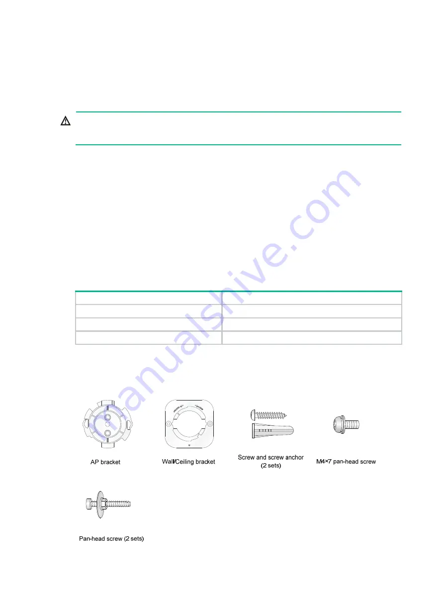
Installation accessories 

Figure 1 Accessories provided with the AP 


Содержание WA530

Страница 1: ...ting the AP on a wall 4 Mounting the AP on a ceiling 7 Connecting the AP to the power source 8 Check before power on 8 Connecting the PoE power supply 8 Connecting the local power supply 9 PoE injecto...

Страница 2: ...ion Take adequate safety measures to avoid body injury and device damage Place the AP in a dry and flat location and take anti slip measures Keep the AP clean and dust free Do not place the AP in a mo...

Страница 3: ...2 Installation tools When installing the AP you might need the following tools Prepare the installation tools as required Figure 2 Installation tools...

Страница 4: ...termining the installation position Determine the installation position by observing the following principles Few obstacles such as wall exist between the AP and clients The AP is far away from electr...

Страница 5: ...ng attach the AP bracket to the AP and the wall ceiling bracket to the wall or ceiling Figure 4 Mounting bracket kit 1 AP bracket 2 Alignment peg 3 Wall Ceiling bracket 4 Installation hole Figure 5 Wa...

Страница 6: ...ure 7 Marking installation holes on the wall 3 Drill holes with a diameter of 6 mm 0 24 in and a depth of 30 mm 1 18 in in the marked locations as shown in Figure 8 Figure 8 Drilling holes in the wall...

Страница 7: ...he screw anchors Adjust the position of the wall ceiling bracket and fasten the screws Figure 10 Attaching the wall ceiling bracket to the wall 6 Align the two tabs on the AP bracket into the notches...

Страница 8: ...ket to the AP through the installation hole in the middle of the AP bracket 2 Mark the installation holes on the ceiling by using the wall ceiling bracket 3 Drill two holes with a diameter of 5 mm 0 2...

Страница 9: ...efore powering on the AP To power the AP with local power make sure the local power supply is reliably grounded To power the AP through PoE make sure the PoE power supply PSE is reliably grounded To p...

Страница 10: ...er port of the AP to the local power source Connect the power adapter to the AP as shown in Figure 16 Figure 16 Connecting the local power supply PoE injector power supply CAUTION A PoE injector must...

Страница 11: ...less client with the AP and verify that the client can access resources in the external network For a fit AP execute the display wlan ap all command on the AC and verify that the AP status is R M Sysn...

Страница 12: ...11 C Config DC DataCheck R Run M Master B Backup AP name APID State Model Serial ID ap1 1 R M WA530 219801A1NR8182031202...

Страница 13: ...s enter the username and password and then lick Login The default username and password are admin and h3capadmin respectively Figure 18 Login page Accessing the cloud AP from the Oasis platform By def...

Страница 14: ...13 Figure 19 Oasis Manager QR code 2 Add the AP to the Oasis platform For more information see the H3C Oasis Platform Deployment Guide...

Страница 15: ...ure 20 Fit AP networking Figure 21 Cloud AP networking Table 3 Technical specifications Item Specifications Protocol IEEE 802 11a b g n ac Wave2 Radio Two Built in antenna 2 4 G antenna 3 84 dBi peak...

Страница 16: ...description Port Standards and protocols Description Console port RS EIA 232 The console port is used for device configuration and management GE1 PoE IEEE802 3 IEEE802 3u IEEE802 3af The port acts as...

Страница 17: ...at 1 GHz Only the 5G radio has associated clients Alternating between green and blue at 1 Hz Both the 2 4G and 5G radios have associated clients Table 6 LED description cloud AP mode LED Status Descri...

Отзывы: