H3C WA4320X Скачать руководство пользователя страница 28


21 

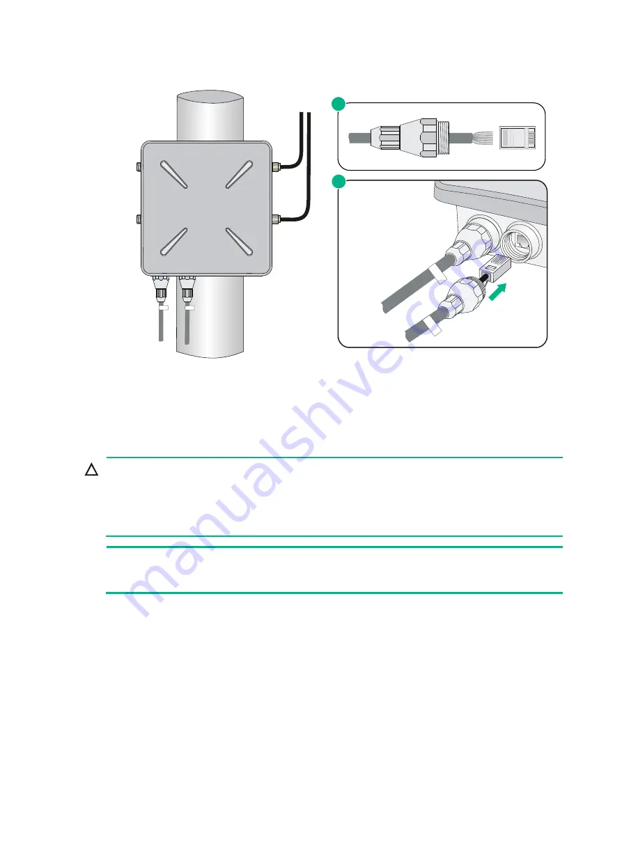
Figure 23 Connecting the copper cable to the copper port of the AP 


4. 

Loosen the sealing nut, tighten the liquid tight adapter, and then tighten the sealing nut. 

5. 

Seal the connection with waterproof sealing tape. 

Connecting the AP to the power supply 


CAUTION: 


Make sure the installation of the AP is complete before powering on the AP. 


Make sure the power injector is well fixed and has good ventilation and heat dissipation performance. 


If multiple power injectors are installed in the same equipment room or low voltage silo, use a power strip 
connected to the backup air switch of the AC box to power the injectors. 


NOTE: 

Put the power injector at the switch side, and the switch connected to the power injector does not 
need to be PoE+ capable. 


The AP can be powered by a power injector. 

To connect the power injector to the AP as shown in 

Figure 22

1. 

Connect the power input line to an AC power supply. 

2. 

Connect the signal & power output line to the copper port of the AP. 

3. 

Connect the signal input line to a switch or an access controller. 

4. 

Ground the grounding terminal of the power injector. 

Labeling cables 

After cable connecting, paste labels on each cable as a best practice for future maintenance: 

Sealing nut

Liquid tight 
adapter

1

2

Содержание WA4320X

Страница 1: ...H3C WA4320X Access Point Installation Guide Hangzhou H3C Technologies Co Ltd http www h3c com Document version 6W100 20170210 ...

Страница 2: ...All other trademarks that may be mentioned in this manual are the property of their respective owners Notice The information in this document is subject to change without notice Every effort has been made in the preparation of this document to ensure accuracy of the contents but all statements information and recommendations in this document do not constitute the warranty of any kind express or im...

Страница 3: ... represents commands and keywords that you enter literally as shown Italic Italic text represents arguments that you replace with actual values Square brackets enclose syntax choices keywords or arguments that are optional x y Braces enclose a set of required syntax choices separated by vertical bars from which you select one x y Square brackets enclose a set of optional syntax choices separated b...

Страница 4: ...OTE An alert that contains additional or supplementary information TIP An alert that provides helpful information Network topology icons Convention Description Represents a generic network device such as a router switch or firewall Represents a routing capable device such as a router or Layer 3 switch Represents a generic switch such as a Layer 2 or Layer 3 switch or a router that supports Layer 2...

Страница 5: ...dware installation and hardware specifications H3C Pluggable SFP SFP XFP Transceiver Modules Installation Guide Guides you through installing SFP SFP XFP transceiver modules Software configuration Configuration guides Describe software features and configuration procedures Command references Provide a quick reference to all available commands Configuration examples Describe typical network scenari...

Страница 6: ...s solutions Technical Support Software Download Provides the documentation released with the software version Technical support service h3c com http www h3c com Documentation feedback You can e mail your comments about product documentation to info h3c com We appreciate your comments ...

Страница 7: ... Installing a directional antenna on a pole 12 Installing the omnidirectional antennas on poles 15 Connecting cables 16 Connecting the antenna cables 17 Connecting the fiber cable 17 Connecting the Ethernet cable 18 Connecting the AP to the power supply 21 Labeling cables 21 Verifying the installation 22 Powering on the AP 22 Verifying the network connection 23 Verifying network connection for the...

Страница 8: ...ers Figure 1 Deployment of WA4320X APs in fit AP mode Figure 2 Deployment of WA4320X APs in fat AP mode Table 1 H3C WA4320X specifications Item Specification Dimensions H W D 86 5 245 245 mm 3 41 9 65 9 65 in Weight 2 kg 4 41 lb Power consumption 8 W standby to 36 W maximum Protocols and materials IEEE802 11a b g n ac Waterproof cast aluminum plastic housing WA4320X Core equipment room RADIUS serv...

Страница 9: ... interference sources heavy duty radars radio stations or electrical substations unstable voltage heavy vibration or loud noise The installation site must be dry without any leakage dripping or dew Temperature and humidity requirements Item Specification Operating temperature 40 C to 65 C 40 F to 149 F Storage temperature 40 C to 85 C 40 F to 185 F Operating humidity noncondensing 0 to 100 Storage...

Страница 10: ...e as short as possible and must not be coiled Make sure that the grounding terminals of all the lightning arresters of the AP and the peer device of the AP are reliably grounded Grounding lead in A grounding lead in is a metal conductor connecting a grounding net and a grounding strip The grounding cable of the AP must be connected to the grounding strip The grounding lead in must be 30 m 98 43 ft...

Страница 11: ... with the AP Liquid tight adapter and sealing nut Sealing plug Console cable for fat AP only Grounding cable Table 4 Accessories not provided with the AP Mounting bracket Pole fixed plate Long bolt flat washer spring washer nut M6 x 12 screw Expansion screw ...

Страница 12: ...ou may need the following tools Prepare these tools and equipment yourself Pickaxe Shovel Adjustable wrench Wire clippers Crystal head crimping pliers Wire stripping pliers Crimping pliers Phillips screwdriver Waterproof sealing tape Fiber fusion splicer Ladder ...

Страница 13: ...le make sure the pole is vertical to the ground and has been treated with corrosion protection Make sure the installation height and position meet the design requirements If you pole mount the AP on a rooftop make sure the pole does not project from the wall of the building and the AP does not suspend in midair To avoid high temperature caused by exposure to the sun install the AP in a place witho...

Страница 14: ... 3 Pole fixed plate 4 Flat washer 5 Spring washer 6 Nut To install the AP on a pole 1 Vertically fix the pedestal of the pole to the rooftop or a cement pier on the rooftop with expansion screws Figure 4 Pole and pedestal 2 Fix the mounting bracket to the pole ...

Страница 15: ...e two upper screw holes on the AP rear Do not fasten the screws all the way in Figure 6 Installing two screws into the two upper screw holes 4 Insert the two M6 12 screws through the mounting holes on the mounting bracket and press the AP downward to fix the AP onto the mounting bracket ...

Страница 16: ...ure 7 Fixing the AP onto the mounting bracket 1 5 Insert the other two M6 12 screws through the two lower mounting holes and fasten the four screws tightly Figure 8 Fixing the AP onto the mounting bracket 2 ...

Страница 17: ...eter of 8 mm 0 31 in and a minimum depth of 60 mm 2 36 in in the marked positions Insert an expansion screw into each hole and tap the expansion screw with a rubber hammer until it is all flush with the wall surface as shown in Figure 10 When you drill holes follow these restrictions and guidelines Hold the drill handle with both hands with the bit vertical to the wall surface and prevent wall dam...

Страница 18: ...re 11 Figure 11 Attaching the mounting bracket to the wall 4 Install two M6 12 screws into the two upper screw holes on the AP rear Do not fasten the screws all the way in 5 Insert the two screws through the mounting holes on the mounting bracket and press the AP downward to fix the AP onto the mounting bracket ...

Страница 19: ...tdoor antennas follow these restrictions and guidelines Keep the AP far from high power electronic equipment and make sure there are no large obstacles and metal objects in the wireless coverage Make sure the antenna mounting bracket is stably mounted on the pole that is vertical to the ground Use oxidation resistant metal materials Fix the pedestal of the antenna pole to a cement pier or add weig...

Страница 20: ...on a parapet with expansion screws and fix the directional antenna on the pole with the pole mounting bracket See Figure 13 Figure 13 Installing a directional antenna on a parapet 1 If there are parapets on the rooftop and the height of the parapets is less than 1 2 m 3 94 ft you can fix the pole on a parapet at one point with expansion screws and fix the bottom end of the pole to the rooftop surf...

Страница 21: ...wires Then install the directional antenna on the pole as shown in Figure 15 Figure 15 Installing a directional antenna on a parapet 3 3 Connect the pole to a grounding grid with a flat steel bar 40 x 4 mm or 1 57 x 0 16 in 4 Fix the antenna on the pole with the pole mounting bracket Cement pier Steel wire Pole Directional outdoor antenna Lightning rod Pole mounting bracket Flat steel bar To the g...

Страница 22: ...main within the shielding angle 45 of the lightning rod Omnidirectional antennas must be kept a minimum of one meter 3 28 ft away horizontally from metal objects Therefore do not weld the lightning rod on a pole attached with an antenna Install the lightning rod on a separate pole between the two omnidirectional antennas and ensure that the antennas are within the shielding angle of the lightning ...

Страница 23: ...y cracks and are not broken To avoid high current and high electromagnetic interference do not place the cables together with heavy current pipelines fire mains or building lightning rods As a best practice use PVC iron or Plica tubes or wire casings connected by flexible pipes or joints for cable deployment Place the tubes or casings against the wall and use cable ties hangers or angle steel bars...

Страница 24: ... reliably grounded during outdoor deployment You can order the standard ready made antenna cables or order cables of desired lengths and N type antenna connectors and make antenna cables on site as needed Test the Voltage Standing Wave Ratio VSWR of the antenna connectors and cables made on site The cable reflectivity on the working channel must meet the requirements of the AP and the engineering ...

Страница 25: ...ceiving port RX of the AP and must be connected to the transmitting port TX of the peer device the one marked as B is the TX port of the AP and must be connected to the RX port of the peer device Typically fiber termination boxes are not waterproof Put the fiber termination box indoor or in a waterproof cabinet If the fiber is connected to a fiber connector box cut off the SC connector and splice ...

Страница 26: ...19 Figure 20 Connecting a copper cable Figure 21 Connecting a fiber cable ...

Страница 27: ...ent 3 kA 8 20 μs IMPORTANT If the fiber port acts as the uplink port the copper port can only provide PoE services and does not transmit data The Ethernet port marked with Signal power output on the power injector must be connected to copper port on the AP 2 Insert the copper cable through the liquid tight adapter and crimp an RJ 45 connector on the end of the cable For more information about crim...

Страница 28: ...age silo use a power strip connected to the backup air switch of the AC box to power the injectors NOTE Put the power injector at the switch side and the switch connected to the power injector does not need to be PoE capable The AP can be powered by a power injector To connect the power injector to the AP as shown in Figure 22 1 Connect the power input line to an AC power supply 2 Connect the sign...

Страница 29: ... After the installation and cabling check the following items before powering on the AP The power supply meets the power specification of the AP The AP is reliably grounded The Ethernet cables are correctly connected The outdoor antennas are installed The cables are correctly labeled The unused ports on the AP are sealed with waterproof plugs Powering on the AP Make sure that all the cables are co...

Страница 30: ...ber of connected auto APs 0 Total number of connected common APs 1 Total number of connected WTUs 0 Total number of inside APs 0 Maximum supported APs 3072 Remaining APs 3070 Total AP licenses 128 Remaining AP licenses 127 AP information State I Idle J Join JA JoinAck IL ImageLoad C Config DC DataCheck R Run M Master B Backup AP name APID State Model Serial ID ap1 1 R WA4320X 219801A0REM153000023 ...

Страница 31: ... the following items before logging in through the console port An 8 core console cable with a crimped RJ 45 connector at one end and a DB 9 connector at the other end A configuration terminal with a serial port such as a laptop or PC Setting up the configuration environment CAUTION The serial ports on PCs do not support hot swapping To connect a PC to an operating device first connect the PC end ...

Страница 32: ...default login information Username admin Password h3capadmin IP address of VLAN interface 1 of the AP 192 168 0 50 with subnet mask 255 255 255 0 If the default IP address is changed perform either of the following tasks Contact the administrator to get the new IP address Log in to the AP from the console port and execute the display vlan 1 command to view the IP address NOTE For more information ...

Страница 33: ...i Contents Appendix A LEDs and ports 1 LEDs 1 Ports 2 ...

Страница 34: ... Flashing green 0 5 Hz The AP is booting Flashing green 1 Hz The AP is in idle state Steady yellow Software loading fails Off The AP is powered off or operates incorrectly ETH1 10 100M 10 100 M Ethernet port LED Steady green A 10 100 Mbps link is present on the port Flashing green A 10 100 Mbps link is being established Off No 10 100 Mbps link is present on the port ...

Страница 35: ... Flashing green 1 Hz A link is being established on the port Off No link is present on the port 2 4G 802 11b g n LED Steady green The wireless link is operating correctly Off The wireless link is down or fails 5G 802 11a n ac LED Steady green The wireless link is operating correctly Off The wireless link is down or fails Ports The AP provides two 2 4 GHz antenna ports and two 5 0 GHz antenna ports...

Страница 36: ...rt 5 ETH1 SFP 100 1000BASE FX fiber port 6 ETH1 10 100 1000BASE TX copper port 7 Grounding terminal 8 Console port Table 2 Port description Port Standards and protocols Description ETH1 SFP 100 1000BASE FX Ethernet fiber port IEEE802 3 SFP MSA SFF 8472 Connects to the Internet or Metropolitan Area Network MAN ...

Страница 37: ...Ethernet copper port IEEE802 3 IEEE802 3u Connects to the Internet or MAN and acts as a PoE port 2 4G 1 2 IEEE802 11b g n Antenna port for 2 4 GHz band 5G 1 2 IEEE802 11a n ac Antenna port for 5 GHz band CONSOLE RS EIA 232 Console port for configuration and management ...

Страница 38: ...i Contents Appendix B Crimping an RJ 45 connector 1 ...

Страница 39: ...ght through cable is usually used to connect PC or router to hub or switch Crossover cable The colored wires are of different sequences at the two ends of the cable A crossover cable is usually used to connect PC to PC router to router or PC to router Table 1 Straight through cable pin outs RJ45 pin Signal Wire Signal direction RJ45 pin 1 TX White orange Æ 1 2 TX Orange Æ 2 3 RX White green Å 3 4 ...

Страница 40: ... 7 8 Brown 8 NOTE The Ethernet ports of the AP are autosensing and can recognize both types of cables When making a cable follow the exact sequence listed in Table 1 or Table 2 When the AP is installed outdoors the cable must be waterproof If possible use waterproof tubing to protect the cable ...

Отзывы: