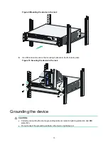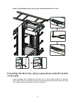
background image

17 

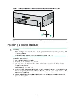
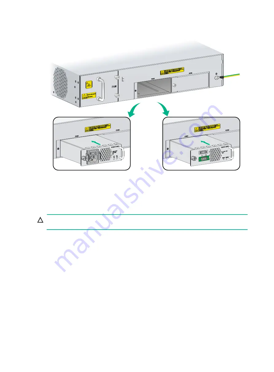
Figure 14 Installing a power module 


Installing optional components 

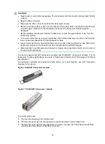
(Optional) Installing an interface module 


CAUTION: 

The NSQ1G24XS60 interface module is available for the device. It is not hot swappable. 


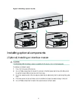
To install an interface module: 

1. 

Face the front panel of the device. 

2. 

Use a Phillips screwdriver to loosen the screws on the filler panel and remove the filler panel. 
Keep the removed filler panel secure for future use. 

3. 

Open the ejector levers on the module and slide the module slowly into the slot along the guide 
rails. 

4. 

Close the ejector levers and make sure the interface module is seated securely in the slot.  

5. 

Use a Phillips screwdriver to fasten the captive screws on the module. 

AC

DC

Содержание SecPath F5020

Страница 1: ...H3C SecPath F5020 F5040 Firewalls Installation Guide New H3C Technologies Co Ltd http www h3c com Document version 6W101 20190329...

Страница 2: ...respective owners Notice The information in this document is subject to change without notice All contents in this document including statements information and recommendations are believed to be acc...

Страница 3: ...kets enclose syntax choices keywords or arguments that are optional x y Braces enclose a set of required syntax choices separated by vertical bars from which you select one x y Square brackets enclose...

Страница 4: ...s a Layer 2 or Layer 3 switch or a router that supports Layer 2 forwarding and other Layer 2 features Represents an access controller a unified wired WLAN module or the access controller engine on a u...

Страница 5: ...Documentation feedback You can e mail your comments about product documentation to info h3c com We appreciate your comments...

Страница 6: ...uried in the earth 15 Installing a power module 16 Installing optional components 17 Optional Installing an interface module 17 Optional Installing network signal lightning arresters 18 Optional Insta...

Страница 7: ...oting the device 37 Troubleshooting 39 Power module failure 39 Fan tray failure 39 Configuration terminal display issue 39 Password loss 40 High operating temperature 40 Software loading failure 40 Ap...

Страница 8: ...is flat vibration free and away from electromagnetic interferences ESD and anti slip measures are in place Do not place the device on an unstable case or desk The device might be severely damaged in...

Страница 9: ...dust plug into any open fiber port or transceiver module port to protect them from contamination and ESD damage Moving safety When you move the device follow these guidelines To avoid damage move and...

Страница 10: ...rature can accelerate the aging of insulation materials and significantly lower the reliability and lifespan of the device Table 2 Temperature and humidity requirements Item Specification Temperature...

Страница 11: ...e Cleanliness Maintain the humidity and temperature at acceptable levels For more information see Temperature and humidity Before working with the device wear an ESD wrist strap or gloves and ESD clot...

Страница 12: ...three wire power receptacle with protection earth PE to filter interference from the power grid Keep the device far away from radio transmitting stations radar stations and high frequency devices Use...

Страница 13: ...x A Chassis views and technical specifications Installation tools No installation tools are provided with the device Prepare them yourself as required Figure 3 Installation tools Crimping tool Phillip...

Страница 14: ...the device is away from the grounding facility of power equipment or lightning protection grounding facility The device is far away from radio transmitting stations radar stations and high frequency...

Страница 15: ...irements Result Tools and accessories Accessories provided with the device are available Installation tools are available Reference Documents shipped with the device are available Online documents are...

Страница 16: ...cover intact and if you want to open the chassis contact the local agent of H3C for permission Otherwise H3C shall not be liable for any consequence caused thereby The installation procedure is simila...

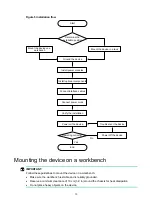
Страница 17: ...cm 3 9 in around the chassis for heat dissipation Do not place heavy objects on the device Yes No Start Ground the device Install power modules Connect power cords Power on the device Troubleshoot th...

Страница 18: ...stalling the device in a standard 19 inch rack WARNING To avoid bodily injury and device damage use a minimum of two persons to install the device CAUTION Ensure a clearance of 1 RU 44 45 mm 1 75 in b...

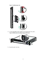
Страница 19: ...12 Figure 7 Installing cage nuts 4 Use the supplied M4 screws to attach the mounting brackets to the device Figure 8 Attaching the mounting brackets to the device 5 Mount the device in the rack...

Страница 20: ...ting brackets to the front rack posts Figure 10 Securing the device to the rack Grounding the device CAUTION Correctly connecting the device grounding cable is crucial to lightning protection and EMI...

Страница 21: ...post and then fasten the nut Figure 11 Grounding the device by using a grounding strip Grounding the device by using the grounding terminal on the rack CAUTION To ground the device by using the ground...

Страница 22: ...grounding conductor buried in the earth If earth is available at the installation site hammer a 0 5 m 1 64 ft or longer angle iron or steel tube into the earth to serve as a grounding conductor Weld...

Страница 23: ...Face the rear panel of the device 2 Select the slot to install the power module 3 Optional Use a Phillips screwdriver to loosen the captive screws on the filler panel and remove the filler panel Skip...

Страница 24: ...nt panel of the device 2 Use a Phillips screwdriver to loosen the screws on the filler panel and remove the filler panel Keep the removed filler panel secure for future use 3 Open the ejector levers o...

Страница 25: ...port is routed from outdoors use a network signal lightning arrester for the port to protect against damages caused by lightning strikes First connect the network cable routed from outdoors to the arr...

Страница 26: ...ou can use either a straight through or a cross over network cable to connect a copper Ethernet port For more information about Ethernet twisted pair cables see Ethernet twisted pair cable To connect...

Страница 27: ...r and a dust plug into any open fiber port or transceiver module port to protect them from contamination and ESD damage Make sure the Tx and Rx ports on a transceiver module are connected to the Rx an...

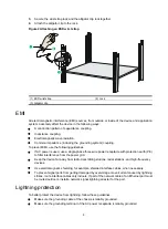
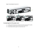
Страница 28: ...efore powering on the device make sure the grounding cable is reliably connected and the power source is powered off Connecting the AC power cord 1 Attach the power cord retainer to the power module a...

Страница 29: ...the DC power cord 1 Correctly orient the DC power cord connector and insert the connector into the receptacle 2 Use a cable tie to secure the DC power cord to the power module handle 3 Connect the ot...

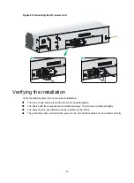
Страница 30: ...installation There is enough space around the device for heat dissipation The device and its components are installed securely The screws are fastened tightly The power source specifications are as r...

Страница 31: ...r source specifications meet the device requirements The console cable is correctly connected the terminal or PC used for configuration has started and the configuration parameters have been correctly...

Страница 32: ...bin is self decompressing Done Line con0 is available Press ENTER to get started Press ENTER to access user view of the device NOTE To access the EXTENDED BOOTWARE menu press Ctrl B immediately when...

Страница 33: ...assword admin IP address of GigabitEthernet 1 0 0 192 168 0 1 24 To log in to the device from the Web interface by using the default account 1 Use an Ethernet cable to connect a PC to Ethernet managem...

Страница 34: ...27 4 Run the Telnet client on the PC and enter the login information...

Страница 35: ...the rear panel of the device 2 Use a Phillips screwdriver to loosen the captive screw on the power module 3 Holding the power module handle with one hand and supporting the module bottom with the oth...

Страница 36: ...ce module install a filler panel in the interface module slot Figure 22 Removing an NSQ1G24XS60 interface module 1 Loosen the captive screws 2 Open the ejector levers 3 Pull the module out of the slot...

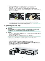
Страница 37: ...lacing the fan tray WARNING The fan tray blades will keep rotating at a high speed for a while after being removed from the operating device To avoid bodily injury do not touch the rotating fan tray b...

Страница 38: ...e with one hand and supporting the fan tray bottom with the other push the fan tray slowly into the slot along the guide rails Make sure the fan tray is seated securely in the slot 5 Use a Phillips sc...

Страница 39: ...e and hardware version information for the device Use the display version command to display software and hardware version information for the device Sysname display version H3C Comware Software Versi...

Страница 40: ...ng the CPU usage of the device Use the display cpu usage command to display the CPU usage of the device Sysname display cpu usage Slot 1 CPU 0 CPU usage 3 in last 5 seconds 3 in last 1 minute 3 in las...

Страница 41: ...be allocated and used for such tasks as running service modules and storing files The size of part 2 equals the total size minus the size of part 1 Used Used physical memory Free Free physical memory...

Страница 42: ...al Speed 3051 Fan 3 Status Normal Speed 3103 Table 10 Output description Field Description Fan Number of the fan Status Fan state Normal The fan is operating correctly Absent The fan is not in positio...

Страница 43: ...ceeds this threshold Displaying the operational statistics of the device When you perform routine maintenance or the system fails you might need to view the operational information of each functional...

Страница 44: ...central wavelength of the laser sent transmission distance and vendor name or name of the vendor who customizes the transceiver modules To display transceiver module information execute the display tr...

Страница 45: ...ta loss or hardware damage It is the least preferred method To reboot the device immediately Task Command Remarks Reboot the device immediately reboot Available in user view To schedule a reboot Task...

Страница 46: ...N FAILED Fan 1 failed The output indicates a fan tray failure Solution To resolve the issue 1 Verify that a fan tray is installed in the fan tray slot 2 Verify that the fan tray is in firm contact wit...

Страница 47: ...PU Use the display environment command to examine whether the temperature of the device keeps rising If the temperature exceeds 90 C 194 F power off the device immediately and contact H3C Support 4 If...

Страница 48: ...100 1000BASE T autosensing copper Ethernet ports Twelve 1000BASE X fiber Ethernet ports Four 10GBASE R fiber Ethernet ports One USB port One console port Figure 26 Front view 1 10 100 1000BASE T copp...

Страница 49: ...em Specification Dimensions H W D excluding rubber feet and mounting brackets 88 1 440 443 1 mm 3 47 17 32 17 44 in Weight full configuration 15 7 kg 34 61 lb Storage media Table 14 Storage media spec...

Страница 50: ...43 Power consumption Table 15 Power consumption Item Specification System power consumption 260 W Fan tray power consumption 45 W NSQ1G24XS60 interface module power consumption 65 W...

Страница 51: ...ports 24 to 29 4 Ejector lever 5 Captive screw Power module The device provides two power module slots PWR1 and PWR2 and comes with a filler panel installed in the PWR2 slot The device supports AC and...

Страница 52: ...60 Hz Maximum input current 4 A Maximum power 300 W DC power module The PSR300 12D2 DC power module is available for the device It provides a maximum output of 300 W Figure 30 PSR300 12D2 DC power mo...

Страница 53: ...perating without a fan tray for more than 2 minutes The RT FANF fan tray is available for the device Table 18 RT FANF fan tray specifications Item Specification Automatic fan speed adjustment Supporte...

Страница 54: ...ation Connector RJ 45 Standard compliant RS 232 Baud rate 9600 bps default to 115200 bps Cable type Common asynchronous serial port cable Transmission distance 15 m 49 21 ft Services Connection to an...

Страница 55: ...23 1000BASE X SFP transceiver modules available for the 1000BASE X fiber ports Transceiver module Central wavelength Connect or Fiber Max transmission distance SFP GE SX MM850 A 850 nm LC 62 5 125 m...

Страница 56: ...ule Central wavelength Connector Fiber Max transmission distance SFP XG SX MM850 A 850 nm LC 50 125 m MMF 300 m 984 3 ft 62 5 125 m MMF 82 m 269 03 ft 66 m 216 54 ft SFP XG LX220 MM131 0 1310 nm LC 62...

Страница 57: ...ot present or is faulty Steady green The power module is operating correctly Copper Ethernet port LED 10 100 1000B ASE T Off No link is present Steady green A link is present Flashing green The port i...

Страница 58: ...ff No link is present Steady green A 1000 Mbps link is present Flashing green The port is receiving and sending data at 1000 Mbps 10GBASE R Off No link is present Steady green A 10 Gbps link is presen...

Страница 59: ...isted copper cables can cancel the electromagnetic radiation of each other and reduce interference of external sources An Ethernet twisted pair cable mainly transmits analog signals and is advantageou...

Страница 60: ...Ethernet twisted pair cable connects network devices through the RJ 45 connectors at the two ends Figure 32 shows the pinouts of an RJ 45 connector Figure 32 RJ 45 connector pinout NOTE The RJ 45 Eth...

Страница 61: ...g to the RJ 45 Ethernet port type on your device An RJ 45 Ethernet port can be MDI for routers and PCs or MDIX for switches Table 30 and Table 31 show their pinouts Table 30 RJ 45 MDI port pinouts 10B...

Страница 62: ...ble C To ensure normal communication the pins for sending data on one port must correspond to the pins for receiving data on the peer port When both of the ports on the two devices are MDI or MDIX use...

Страница 63: ...tance of several thousand meters Uses LEDs as the light source often within LANs or distances of a couple hundred meters within a campus network Table 33 Allowed maximum tensile force and crush load P...

Страница 64: ...ve a fiber when connecting it If the fiber has to pass through a metallic board hole when passing through a metallic board hole or bending along the acute side of mechanical parts the fiber must wear...

Отзывы: