IBM Security SiteProtector System SP3001 Getting Started
Guide
This document guides you through the process of connecting and performing the initial configuration of
your IBM
®
Security SiteProtector
™
System SP3001 appliance.
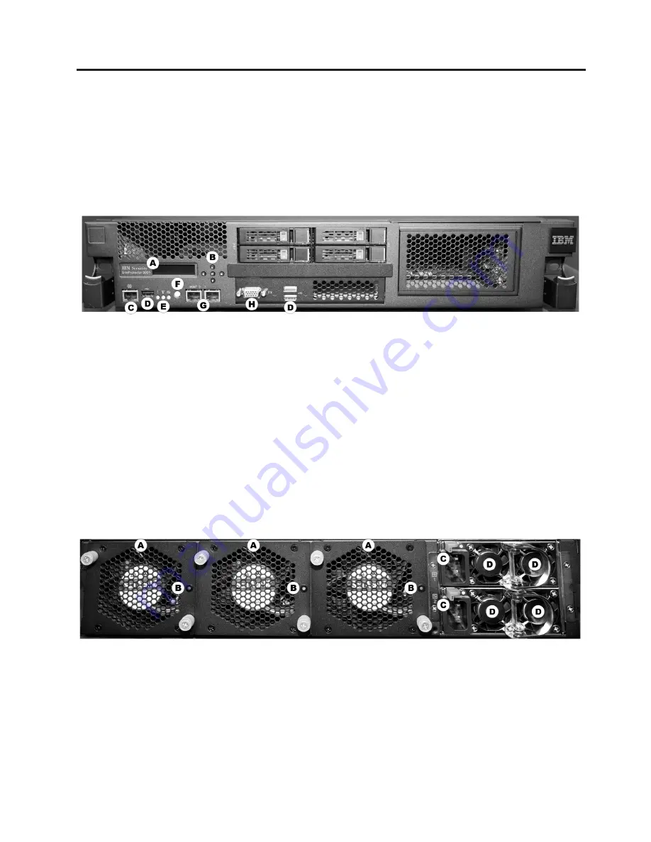
Front panel
Front panel features
v
A: LCD panel -
use for initial network configuration, restarting or shutting down the appliance,
viewing the serial number of the appliance, and setting the appliance PIN.
v
B: Arrow and enter keys -
use to select menu choices and interact with the appliance using the LCD
panel.
v
C: Serial console RJ-45 port -
use for optional terminal-based setup, diagnostic testing, and recovery.
v
D: USB ports (3) -
for keyboard, mouse, and external DVD-ROM to retrieve data and install firmware.
v
E: Indicators -
to display status for alerts (amber), system ID (blue), and power (green) respectively.
v
F: Power switch -
to power the unit on or off.
v
G: Management interfaces (2 GbE NICs) -
use Management port 0 to manage the SiteProtector
appliance; management port 1 is unused. The Management port handles all network communication.
v
H: VGA video port -
for external monitor.
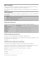
Rear panel
Rear panel features
v
A: Cooling fans (3)
v
B: Cooling fan status indicators (3)
v
C: Power connections (2)
v
D: Power supplies (4)
© Copyright IBM Corp. 2009, 2014
1


