background image


9-1 

Appendix C Cables 

Console cable 

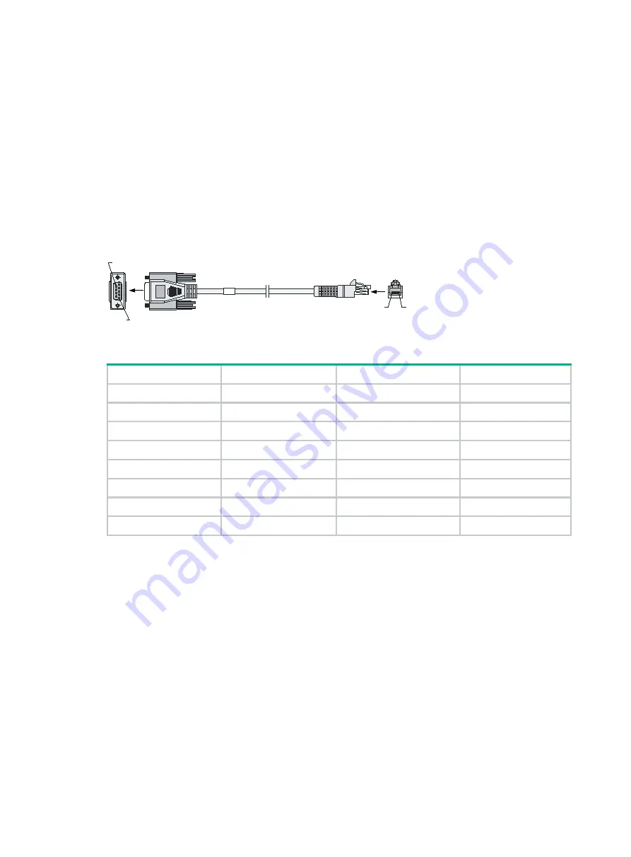
A console cable is an 8-core shielded cable with a crimped RJ-45 connector at one end and a DB-9 
female connector at the other end. The RJ-45 connector is for connecting to the console port of the 
firewall, and the DB-9 female connector is for connecting to the serial port on the configuration 
terminal. 

Figure9-1 Console cable 


Table9-1 Console cable pinouts 

RJ-45 

Signal 

Direction 

DB-9 

RTS 

← 

DTR 

← 

TXD 

← 

CD 

→ 

GND 

RXD 

→ 

DSR 

→ 

CTS 

→ 


Ethernet twisted pair cable 

Introduction 

An Ethernet twisted pair cable consists of four pairs of insulated copper wires twisted together. Every 
wire uses a different color, and has a diameter of about 1 mm (0.04 in). A pair of twisted copper 
cables can cancel the electromagnetic radiation of each other, and reduce interference of external 
sources. An Ethernet twisted pair cable mainly transmits analog signals and is advantageous in 
transmitting data over shorter distances. It is the commonly used transmission media of the Ethernet. 
The maximum transmission distance of the Ethernet twisted pair cable is 100 m (328.08 ft). To 
extend the transmission distance, you can connect two twisted pair cable segments with a repeater. 
At most four repeaters can be added, which means five segments can be joined together to provide 
a transmission distance of 500 m (1640.42 ft).  

Ethernet twisted pair cables can be classified into category 3, category 4, category 5, category 5e, 
category 6, and category 7 cables based on performance. In LANs, category 5, category 5e, and 
category 6 are commonly used.  

W

B

Pos.8

Pos.1

B

A

Pos.9

Pos.1

A

Содержание SecPath F1000-AI-5 Series

Страница 1: ...replace with actual values Square brackets enclose syntax choices keywords or arguments that are optional x y Braces enclose a set of required syntax choices separated by vertical bars from which you...

Страница 2: ...work device such as a router switch or firewall Represents a routing capable device such as a router or Layer 3 switch Represents a generic switch such as a Layer 2 or Layer 3 switch or a router that...

Страница 3: ...ardware model configuration or software version It is normal that the port numbers sample output screenshots and other information in the examples differ from what you have on your device Documentatio...

Страница 4: ...g terminal on the rack 16 Installing a power supply 17 Installing an interface module 18 Installing a drive 19 Installing a drive for an F1000 AI 15 firewall 19 Installing a drive for other firewalls...

Страница 5: ...ue 6 40 Password loss 6 40 Cooling system failure 6 41 Software loading failure 6 41 7 Appendix A Chassis views and technical specifications 1 Chassis views 1 F1000 AI 05 1 F1000 AI 15 1 F1000 AI 25 F...

Страница 6: ...iii Optical fiber 9 5...

Страница 7: ...oss data corruption or damage to hardware or software General safety recommendations Do not place the firewall on an unstable case or desk The firewall might be severely damaged in case of a fall Make...

Страница 8: ...in interface view to disable the optical source Install dust caps to disconnected optical fiber connectors and ports on disconnected transceiver modules to avoid damage caused by built up dust Insert...

Страница 9: ...t failure High temperature can accelerate the aging of insulation materials and significantly lower the reliability and lifespan of the firewall For the temperature and humidity requirements of the fi...

Страница 10: ...te has a good cooling system When installing the firewall in a standard 19 inch rack reserve a distance of 1U 44 45 mm or 1 75 in between the chassis and other devices The F1000 AI 05 firewall cools i...

Страница 11: ...ESD wrist strap is provided with the firewall Purchase one yourself Before you attach an ESD wrist strap make sure the rack or the workbench is reliably grounded To attach the ESD wrist strap 1 Wear t...

Страница 12: ...e port Lightning protection To protect the firewall from lightning better follow these guidelines Make sure the grounding cable of the chassis is reliably grounded Make sure the grounding terminal of...

Страница 13: ...to 40 C 41 F to 104 F Storage 40 C to 70 C 40 F to 158 F Relative humidity Operating Without drives 5 RH to 95 RH noncondensing With drives 10 RH to 90 RH noncondensing Storage 5 RH to 95 RH nonconden...

Страница 14: ...ate the power switch in the equipment room In case of emergency during operation switch off the power switch Rack mounting requirements Make sure the cabinet is equipped with a good ventilation system...

Страница 15: ...open the chassis contact H3C for permission Otherwise H3C shall not be liable for any consequence The installation procedure is similar for the F1000 AI 05 F1000 AI 15 F1000 AI 25 F1000 AI 35 F1000 AI...

Страница 16: ...ndard 19 inch rack is not available you can place the firewall on a workbench To mount the firewall on a workbench 1 Verify that the workbench is sturdy and reliably grounded End Determine the install...

Страница 17: ...dissipation ensure a minimum clearance of 80 mm 3 15 in around the air inlet and outlet vents of the chassis and a distance of 1U 44 45 mm or 1 75 in between the chassis and other devices in the rack...

Страница 18: ...ides of the firewall with M4 screws provided with the firewall Figure2 4 Attaching the front mounting brackets to the firewall 6 Mount the firewall in the rack Use M6 screws to secure the mounting bra...

Страница 19: ...ng brackets 4 Install cage nuts Figure2 6 Installing cage nuts 5 Attach the front mounting brackets and shoulder screws to both sides of the firewall with M4 screws provided with the firewall Figure2...

Страница 20: ...m 6 02 in between the rear rack posts and the interior side of the rack door Figure2 8 Attaching the rear mounting brackets to the rear rack posts with the wide flange inside the rack Figure2 9 Attach...

Страница 21: ...re2 11 Mounting the firewall in the rack with the wide flange of the rear mounting brackets outside the rack Grounding the firewall WARNING Correctly connecting the firewall grounding cable is crucial...

Страница 22: ...x nut from the grounding strip 5 Use a pair of needle nose pliers to bend a hook at the other end of the grounding cable Attach the hook to the grounding point and secure the hook with a screw Figure2...

Страница 23: ...lies To install a power supply 1 Face the rear panel of the firewall 2 Remove the filler panel if any from the target power supply slot The firewall comes with the PWR1 slot empty and the PWR0 slot in...

Страница 24: ...ctor levers of the interface module before inserting it into slot 2 No interface modules are provided with the firewall Purchase them as needed For interface module compatibility with the firewalls se...

Страница 25: ...void damage to drives always hold a drive by its sides Do not touch any components and do not squeeze vibrate or strike a drive Install a filler panel in empty drive slots to prevent dust and ESD dama...

Страница 26: ...0 Installing a drive Connecting Ethernet cables Connecting a copper Ethernet port You can use either a straight through or a cross over network cable For more information about Ethernet twisted pair c...

Страница 27: ...nsceiver module connected with a fiber into a fiber port To connect an optical fiber first install the transceiver module in the fiber port and then connect the fiber Insert a dust plug into any open...

Страница 28: ...onnecting an optical fiber Connecting power cords CAUTION Make sure the grounding cable of the firewall is correctly connected and the power source is powered off before connecting the power cord Conn...

Страница 29: ...a releasable cable tie see Figure2 26 to secure the power cord 3 Connect the other end of the power cord to an AC power source Figure2 25 Connecting an AC power cord using a power cord retainer clip t...

Страница 30: ...ower cord Verifying the installation Verify the following items to ensure correct installation There is enough space for heat dissipation around the firewall The firewall and its components are instal...

Страница 31: ...ing the firewall Pre start checking WARNING Locate the emergency power off switch in the room before powering on the firewall so you can quickly shut power off when an electrical accident occurs Befor...

Страница 32: ...ed Date Aug 2 2021 Memory Type DDR4 SDRAM Memory Size 8152MB Memory Speed 1037MHz flash Size 3728MB CPLD 1 Version 0 0 CPLD 2 Version 1 0 PCB 1 Version Ver A PCB 2 Version Ver A Press Ctrl B to access...

Страница 33: ...hows the default Web interface login information Table3 1 Default Web interface login information Item Default configurations Username admin Password admin Management Ethernet port F1000 AI 05 F1000 A...

Страница 34: ...de user role and common properties in VTY user line view By default the authentication mode is scheme and the username and password are admin 3 Connect a PC to the management Ethernet port M GigabitEt...

Страница 35: ...one hand and pull the power supply part way out of the slot 4 Supporting the bottom of the power supply with the other hand gently pull the power supply out of the slot along the slide rails Figure4...

Страница 36: ...odule For the installation procedure see Installing an interface module If you are not to install a new interface module install a filler panel in the slot to ensure good ventilation in the firewall F...

Страница 37: ...ive If you are not to install a new drive in the slot install a filler panel in the slot to prevent dust and ensure good ventilation Figure4 4 Removing a drive Replacing a transceiver module WARNING D...

Страница 38: ...tors 3 Pivot the clasp of the transceiver module down to the horizontal position and gently pull the transceiver module out Figure4 6 Removing the transceiver module 4 Install dust caps to the removed...

Страница 39: ...9 0 CFCard Num 0 Displaying the software and hardware version information for the firewall Use the display version command to display software and hardware version information for the firewall Sysname...

Страница 40: ...lay the electrical label information for the firewall Sysname display device manuinfo Slot 1 CPU 0 DEVICE_NAME F1000 AI 65 DEVICE_SERIAL_NUMBER 210235A2H79196Q0000B MAC_ADDRESS 0868 8DBC 3B73 MANUFACT...

Страница 41: ...usage at the interval of 1 minute 3 in last 5 minutes Average CPU usage in the last 5 minutes After the firewall boots the firewall calculates and records the average CPU usage at the interval of 5 mi...

Страница 42: ...splay environment command to display the temperature information of the firewall Sysname display environment System Temperature information degree centigrade Slot Sensor Temperature LowerLimit Warning...

Страница 43: ...07 155002 tar gz Please wait Save successfully To view the diag gz file a In user view execute the tar extract archive file diag tar gz command and then the gunzip diag gz command to decompress the fi...

Страница 44: ...firewall prompts REBOOT IN ONE MINUTE and reboots in one minute If you are performing file operations when the firewall is to be rebooted the system does not execute the reboot command for security T...

Страница 45: ...5 39 Task Command Remarks and specify a reboot waiting time scheduler reboot delay...

Страница 46: ...arbled text when the firewall is powered on Solution To solve the issue 1 Verify that the power supply system is operating correctly 2 Verify that the console cable is correctly connected 3 Verify tha...

Страница 47: ...ched the shutdown level high temperature alarm threshold the device will shut down automatically Information about the firewall temperature in the display environment command output varies by firewall...

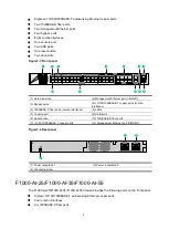
Страница 48: ...ne console port One drive slots Figure7 1 Front panel 1 Hard disk slots 2 Console port 3 USB ports 4 10 100 1000BASE T copper ports combo interfaces 5 Bypass ports 6 10 100 1000BASE T copper ports 7 L...

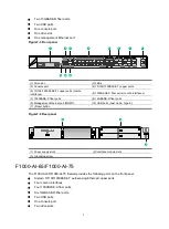
Страница 49: ...es 5 1000BASE X fiber ports combo interfaces 6 LEDs 7 Console port 8 USB ports 9 Reset button 10 10GBASE R fiber ports 11 10 100 1000BASE T copper ports 12 Management Ethernet port 0 MGMT Figure7 4 Re...

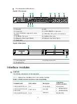
Страница 50: ...8 10GBASE R fiber ports 9 Management Ethernet port MGMT 10 USB ports host mode Type A 11 Reset button Figure7 6 Rear panel 1 Power supply slots 2 Interface module slots 3 Grounding screw F1000 AI 65...

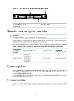
Страница 51: ...ar panel 1 Power supply slots 2 Interface module slots 3 Grounding screw Interface modules CAUTION The interface modules are not hot swappable Table7 1 displays the compatible slots for the interface...

Страница 52: ...two ports in a pair can act as the uplink and downlink interfaces for a Layer 2 link and form a bypass link This enables traffic to be transmitted through the firewall even if the firewall is powered...

Страница 53: ...ith the firewalls and software Network data encryption module Applicable firewalls Applicable slots Applicable software version NSQM1F1KGMC F1000 AI 25 F1000 AI 35 F1000 AI 55 F1000 AI 65 F1000 AI 75...

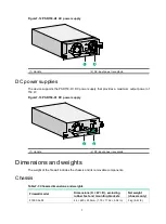
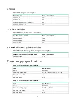
Страница 54: ...Figure7 13 PSR150 D1 DC power supply 1 Handle 2 DC input power receptacle Dimensions and weights The weight of the firewall includes the chassis and its removable components Chassis Table7 3 Chassis...

Страница 55: ...81 in 0 45 kg 0 99 lb NSQM1GP4FBA 19 150 172 9 mm 0 75 5 91 6 81 in 0 42 kg 0 93 lb NS NIM TG6A 19 150 172 9 mm 0 75 5 91 6 81 in 0 40 kg 0 88 lb Network data encryption modules Table7 5 Network data...

Страница 56: ...Network data encryption modules Table7 9 Network data encryption module power consumption Network data encryption module model Power consumption NSQM1F1KGMC 5 7 W Power supply specifications Table7 10...

Страница 57: ...cation Connector RJ 45 Standard compliance 802 3 802 3u and 802 3ab Interface type MDI MDI X autosensing Cable type Category 5 or higher twisted pair cable Transmission distance 100 m 328 08 ft Interf...

Страница 58: ...125 SMF 80 km 49 71 miles SFP GE LH100 SM1550 1550 LC 9 125 SMF 100 km 62 14 miles 10 GE fiber port Table7 16 10 GE fiber port specifications Item Specification Connector type LC Transceiver module ty...

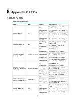
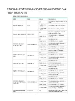
Страница 59: ...The port is receiving and sending data at 1000 Mbps Steady yellow A 10 100 Mbps link is present Flashing yellow The port is receiving and sending data at 10 Mbps or 100 Mbps 10 100 1000BASE T copper p...

Страница 60: ...is present Flashing green The port is receiving and sending data at 1000 Mbps Steady yellow A 10 100 Mbps link is present Flashing yellow The port is receiving and sending data at 10 Mbps or 100 Mbps...

Страница 61: ...00 Mbps 1000BASE X fiber port LED 1000BASE X Off No link is present Steady green A 1000 Mbps link is present Flashing green The port is receiving and sending data at 1000 Mbps 10GE fiber port LED 10GB...

Страница 62: ...4 LED Mark Status Description Steady green The interface module is operating correctly...

Страница 63: ...in A pair of twisted copper cables can cancel the electromagnetic radiation of each other and reduce interference of external sources An Ethernet twisted pair cable mainly transmits analog signals and...

Страница 64: ...Ethernet twisted pair cable connects network devices through the RJ 45 connectors at the two ends Figure9 2 shows the pinouts of an RJ 45 connector Figure9 2 RJ 45 connector pinout NOTE The RJ 45 Eth...

Страница 65: ...Pin 10BASE T 100BASE TX 1000BASE T Signal Function Signal Function 1 Tx Sends data BIDA Bi directional data cable A Straight through cable white orange orange white green blue white blue green white b...

Страница 66: ...cable C To ensure normal communication the pins for sending data on one port must correspond to the pins for receiving data on the peer port When both of the ports on the two devices are MDI or MDIX...

Страница 67: ...source and transmission distance Uses lasers as the light source often within campus backbones for distance of several thousand meters Uses LEDs as the light source often within LANs or distances of...

Страница 68: ...two fiber connectors You can brush the end faces only in one direction Never bend or curve a fiber when connecting it If the fiber has to pass through a metallic board hole when passing through a met...

Страница 69: ...H3C SecPath F1000 AI X5 Firewall Series Installation Guide New H3C Technologies Co Ltd http www h3c com Document version 6W101 20211130...

Страница 70: ...espective owners Notice The information in this document is subject to change without notice All contents in this document including statements information and recommendations are believed to be accur...

Отзывы: