background image

5-36 

Display M-LAG system information. 

display m-lag system 

Display detailed information about M-LAG interfaces. 

display m-lag verbose


[


interface


interface-number


]


CAUTION: 

  In an M-LAG system, all management Ethernet ports on the primary and secondary devices are 

available for use. From the perspective of the network management system, the two devices in 
the M-LAG system are independent and you must log in and manage them separately. 

  To prevent network failures caused by M-LAG system splitting, configure HA after the M-LAG 

system is set up. For more information, see 

H3C Data Center Switches M-LAG Configuration 

Guide


Maintenance and troubleshooting 

Power supply failure 

Symptom 

The status LED on a power supply is not steady green (active state) or flashing green (standby state) 

For more information about the power supply LED, see 

H3C S9820-8C & S9820-8C-SAN Ethernet 

Switches Hardware Information and Specifications

Solution 

To resolve the issue: 

1. 

Verify that the power cord is connected correctly.  

2. 

Verify that the power source is as required by the switch. 

3. 

Verify that the operating temperature of the switch is in the acceptable range and adequate 
ventilation is available for the power supply. 

4. 

If the issue persists, contact H3C Support. 

To replace a power supply, see "

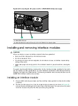
Installing and removing 

.

Fan module failure 


CAUTION: 

The switch has five fan module slots. If multiple fan modules fail when the switch is operating, do not 
remove the fan modules at the same time. Replace the fan modules one after another and finish 
replacing a fan module within 3 minutes. 


Symptom 

The  alarm  LED on a FAN-80B-1-B  fan module  is steady red  and the system outputs alarm 
messages. 

Содержание S9820-8C-SAN

Страница 1: ...H3C S9820 8C S9820 8C SAN Switches Installation Guide New H3C Technologies Co Ltd http www h3c com Document version 6W106 20230727...

Страница 2: ...respective owners Notice The information in this document is subject to change without notice All contents in this document including statements information and recommendations are believed to be acc...

Страница 3: ...ose syntax choices keywords or arguments that are optional x y Braces enclose a set of required syntax choices separated by vertical bars from which you select one x y Square brackets enclose a set of...

Страница 4: ...s a Layer 2 or Layer 3 switch or a router that supports Layer 2 forwarding and other Layer 2 features Represents an access controller a unified wired WLAN module or the access controller engine on a u...

Страница 5: ...Documentation feedback You can e mail your comments about product documentation to info h3c com We appreciate your comments...

Страница 6: ...a power supply 2 19 Removing a power supply 2 20 Connecting the power cord for a power supply 2 21 Installing and removing interface modules 2 22 Installing an interface module 2 22 Removing an inter...

Страница 7: ...ii Symptom 5 36 Solution 5 36 Fan module failure 5 36 Symptom 5 36 Solution 5 37 Configuration terminal display issues 5 37 No output 5 37 Garbled output 5 37...

Страница 8: ...r inlet and outlet vents of the switch free of obstruction Make sure the operating voltage is in the required range To avoid electrical shocks do not open the chassis while the switch is operating As...

Страница 9: ...quirement for cleanliness Substance Particle diameter Concentration limit Dust particles 0 5 m 1 8 10 7 particles m 3 To maintain cleanliness in the equipment room follow these guidelines Keep the equ...

Страница 10: ...ngines separately Do not place them in the same equipment room with the device Make sure the exhausted air of the engines will not flow into the equipment room or towards the air inlet of the air cond...

Страница 11: ...cessory is damaged or lost use its BOM code to purchase a new one You can find the BOM codes for the accessories in Table1 3 Table1 3 Installation accessories BOM code Description Quantity 0223A1B0 Mo...

Страница 12: ...e module filler panel 8 provided 2114A0CK Power supply filler panel 2 provided N A Releasable cable tie As required user supplied 04042967 Console cable Optional 0404A1EE USB to RJ45 console cable Opt...

Страница 13: ...sis cover intact and if you want to open the chassis contact H3C for permission Otherwise H3C shall not be liable for any consequence caused thereby CAUTION When installing the switch always wear an E...

Страница 14: ...cords Verify the installation Turn on the circuit breakers Troubleshoot Operating correctly End No Yes Turn off the circuit breakers Install the switch Attach accessories to the switch and rack Insta...

Страница 15: ...mm 17 32 in Depth 837 mm 32 95 in 760 mm 29 92 in for the chassis 27 mm 1 06 in for the interface module ejector levers 50 mm 1 97 in for the fan module handles 630 to 900 mm 24 80 to 35 43 in A mini...

Страница 16: ...as required See Figure2 5 Bottom support rails not provided 1 kit You must purchase bottom support rails for rack mounting the switch See Figure2 6 Figure2 4 Mounting brackets Figure2 5 Cable managem...

Страница 17: ...attach the mounting bracket to the chassis As a best practice use a torque of 12 kgf cm 1 18 Nm to fasten the M4 screws 3 Attach the other mounting bracket to the other side of the chassis in the same...

Страница 18: ...gn the screw holes in one bottom support rail with the installation holes in the rack posts at one side Use the user supplied M6 screws to attach the bottom support rail to the posts as shown in Figur...

Страница 19: ...ed to the rack posts 3 One person performs the following operations a Supporting the bottom of the switch aligns the chassis with the bottom support rails b Pushes the switch slowly into the rack so t...

Страница 20: ...tch has a cable management frame installed both above and below it To attach a cable management frame to the switch 1 Verify that the cage nuts for securing the cable management frame have been correc...

Страница 21: ...e hole grounding lug to the grounding point on the switch If the grounding cable length or terminal type cannot meet your requirement make an applicable grounding cable or contact H3C Support As shown...

Страница 22: ...EMI protection Connect the grounding cable to the grounding system in the equipment room Do not connect it to a fire main or lightning rod CAUTION To guarantee the grounding effect connect the switch...

Страница 23: ...dissipation of the switch fully configure the switch with fan modules of the same model If the number of installed fan modules is less than the minimum required number the device will output an error...

Страница 24: ...lect appropriate fan modules as needed For the optional fan modules and their specifications see H3C S9820 8C S9820 8C SAN Ethernet Switches Hardware Information and Specifications The switch supports...

Страница 25: ...oving a FAN 80B 1 B fan module Installing and removing power supplies WARNING To avoid bodily injury or device damage strictly follow the procedures in Figure2 19 and Figure2 20 to install and remove...

Страница 26: ...rnal circuit or component of the power supply fails contact H3C Support Installing a power supply The switch supports shipping with fan modules and power supplies installed If your switch came with po...

Страница 27: ...switch is configured with four power supplies removing one or two power supplies does not affect the operation of the switch When the switch has only two power supplies installed removing power suppli...

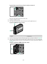
Страница 28: ...PSR1600B 12A B power supply 1 Insert the female connector of the AC power cord supplied with the power supply into the power receptacle on the power supply 2 Use a releasable cable tie to secure the...

Страница 29: ...revent dust from entering the ports The switch provides eight interface module slots For the interface modules available for the switch and the interface module specifications see H3C S9820 8C S9820 8...

Страница 30: ...Figure2 26 LSWM116H interface module 1 Latch 2 Ejector lever 5 Insert the module slowly into the slot along the guide rails as shown by callout 1 in Figure2 27 6 Press down and hold the latch of the...

Страница 31: ...lever to pull the ejector lever out 5 Open the ejector lever to disengage the interface module from the device connector 6 Use both hands to slowly take the module out 7 Place the removed interface m...

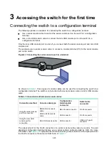
Страница 32: ...ole cables can be used for connecting the switch to a configuration terminal The switch is not provided with a serial console cable or a mini USB console cable Table3 1 Connection methods and console...

Страница 33: ...nnecting to the correct port The serial ports on PCs do not support hot swapping To connect a PC to an operating switch first connect the PC end To disconnect a PC from an operating switch first disco...

Страница 34: ...you must remove and reconnect the USB to RJ45 console cable to the configuration terminal For information about the signal pinout for the RJ 45 connector of a USB to RJ45 console cable see Table3 3 T...

Страница 35: ...er installation wizard 5 Click Finish after the drive installation is completed Figure3 4 Finishing the driver installation 6 Connect the standard USB connector of the cable to the USB port of the con...

Страница 36: ...iguration terminal You can use the emulator program to connect a network device a Telnet site or an SSH site For more information about the terminal emulator programs see the user guides for these pro...

Страница 37: ...3 30...
Страница 38: ...evice supports both the M LAG set and DRNI set of command keywords in the CLI by default The two sets of commands are consistent in the service configuration methods functions and output with only dif...

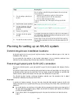
Страница 39: ...the rack for installation of the devices You can place the two switches in one cabinet Alternatively you can install the switches in two cabinets if you re seeking a top of rack access solution in the...

Страница 40: ...rfaces from the related VLANs to avoid loops Do not use the same module to provide interfaces for setting up the keepalive link and peer link Planning the cable connection scheme Select cables or tran...

Страница 41: ...on as shown in Figure4 4 Use transceiver modules and optical fibers for connection if a large distance exists between the member switches Figure4 4 Top of rack connection scheme Configuring the M LAG...

Страница 42: ...nterfaces as M LAG reserved interfaces This ensures that these interfaces will not be MAD down when the peer link fails For more configuration restrictions and guidelines and typical configuration exa...

Страница 43: ...n active state or flashing green standby state For more information about the power supply LED see H3C S9820 8C S9820 8C SAN Ethernet Switches Hardware Information and Specifications Solution To resol...

Страница 44: ...wer system is operating correctly 2 Verify that the console cable is connected correctly 3 Verify that the console cable does not have any problems and the terminal settings are correct 4 If the issue...

Отзывы: